4 • Description of the Controls
28 / 80
80113-401_V24023
2023-05
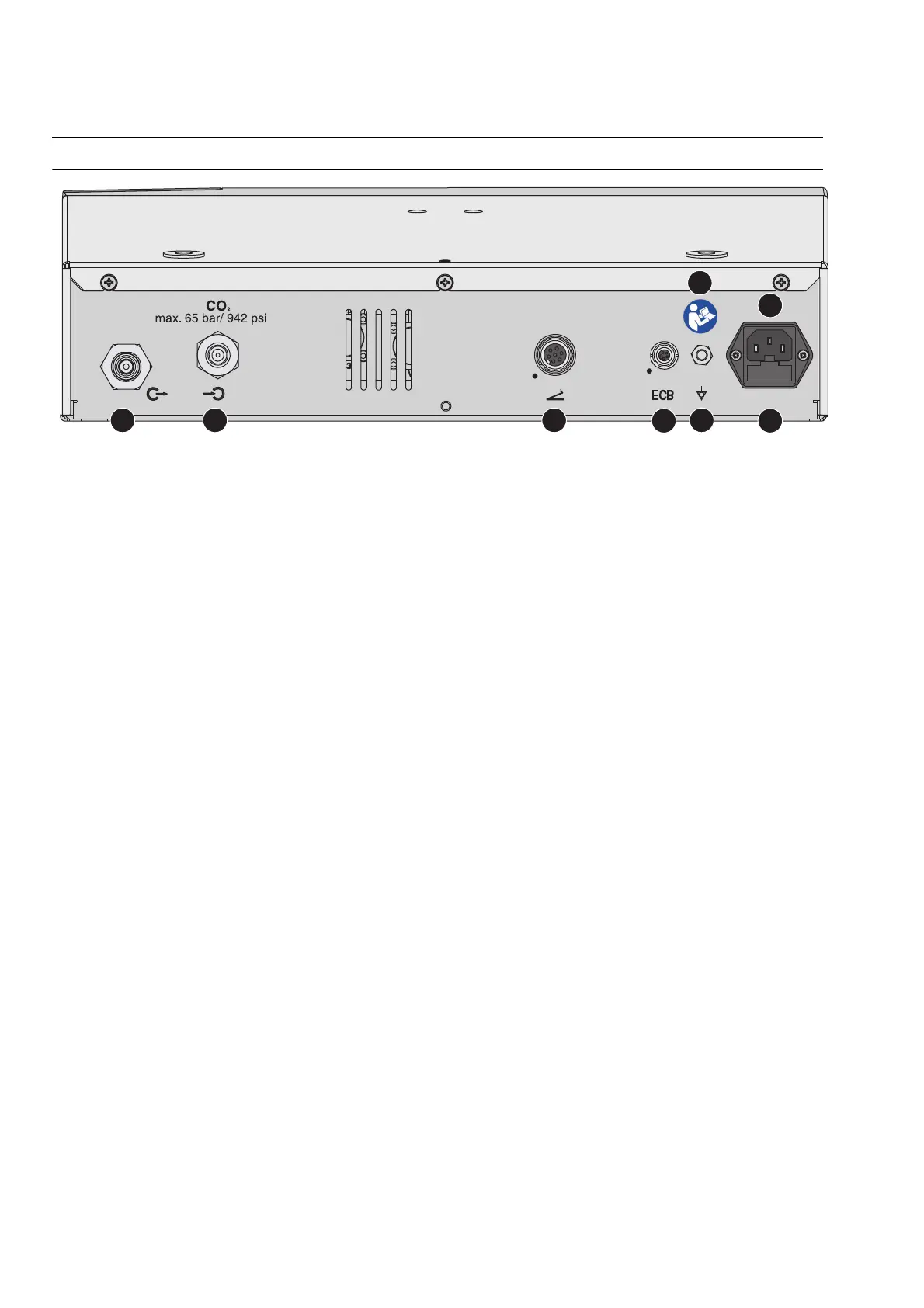
Controls on the back
Fig. 4-2
Gas connections
(1) Waste gas nozzle
For connecting the waste gas tube. Direct the waste gas into the anesthetic suction
system or the open air.
(2) Gas connection
For connecting the gas tube. The gas tube directs the CO
2
from the CO
2
bottle into the
unit. The input pressure may not exceed 65 bar (942 psi).
Sockets
(3) Footswitch socket
For connecting the footswitch.
(4) ECB socket (ECB means Erbe Communication Bus)
Other compatible units can be connected to the unit. The ECB ensures communication
between the units. Insert an ECB cable into these sockets and connect the cable to one
of the other units.
Grounding terminal
(5) Grounding terminal connection
If required, attach a grounding terminal line and connect this to the grounding termi-
nal system of the operating room.
Power connection
(6) Power connection
Connect the unit to a properly installed, grounded power outlet. Use the compatible
Erbe power cord (see the Accessories, Compatible power cords section). If the unit is
installed on an Erbe cart with auxiliary network outlet: Connect the unit to an auxiliary
network outlet. Connect the unit to the mains power using the cart power cord. Follow
the instructions in the user manual for the cart.
Power fuses
(7) Power fuses
The unit is protected with power fuses. If one of these power fuses has blown, the unit
may not be used on the patient again until it has been checked by a competent tech
-
nician. The values of the power fuses are specified on the unit's rating plate. Only
spare fuses with these values may be used.
Symbol
(8)
Read the user manual before switching on and using the unit.