27 / 80
4 • Description of the Controls
80113-401_V24023
2023-05
Chapter 4
Description of the Controls
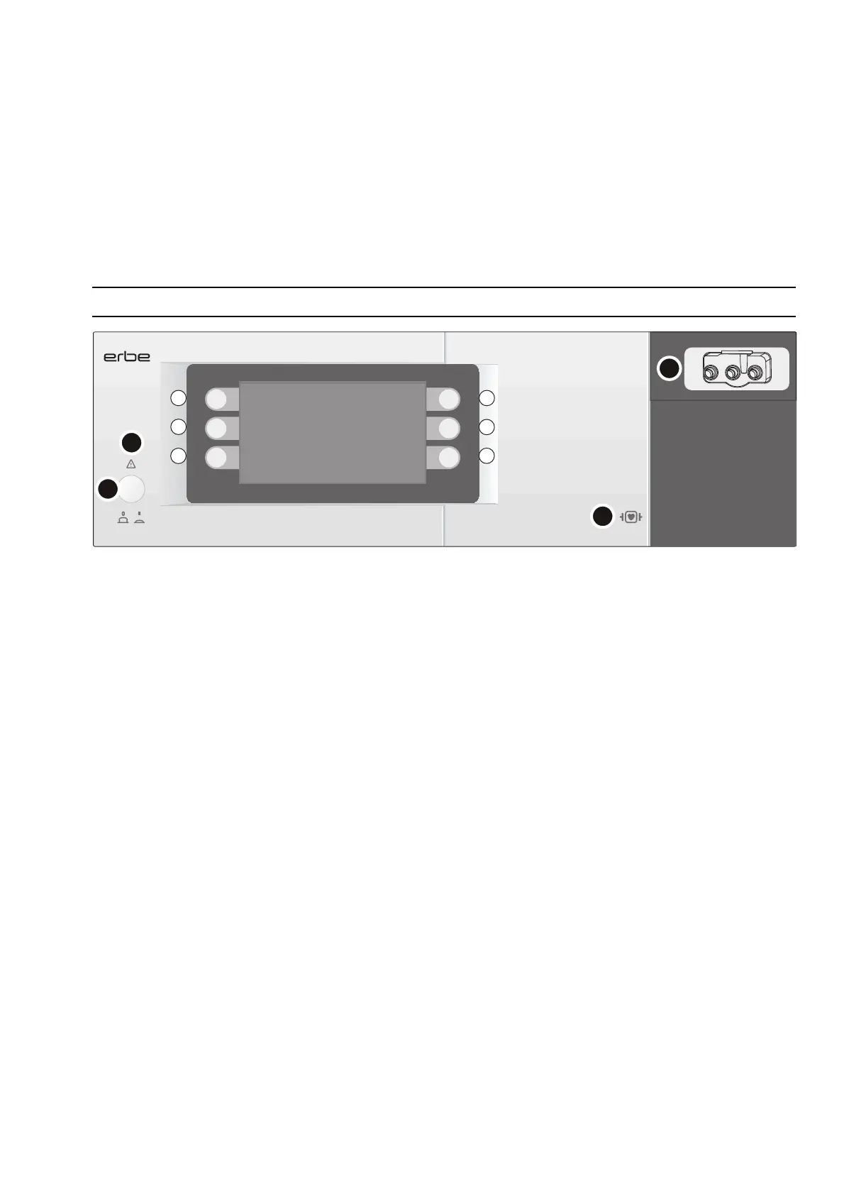
Controls on the front panel
Fig. 4-1
Symbol
(1)
Indicates that the safety instructions in the User Manual must be read before switch-
ing the unit on.
Power
(2) Power switch
Unit on/off. The unit is only fully disconnected from the power supply once the power
plug is pulled out. Install the unit such that the power plug could be easily disconnect
-
ed from the power source.
Selection buttons
(L1) (L2) (L3) (R1) (R2) (R3)
The buttons have a different function depending on which window is shown on the
display. Take note of the function the button refers to.
Symbol
(3) Defibrillation-proof type CF applied part
The applied part conforms to the requirements of type CF (Cardiac Float) and is pro-
tected against the effects of a defibrillator discharge.
Instrument socket
(4) Instrument socket (applied part)
The instrument socket is specific for Erbe. You can only connect Erbe probes to the in-
strument socket. The Erbe probes have instrument recognition.
1
2
3
L1
L2
L3
R1
R2
R3
4
ERBECRYO 2