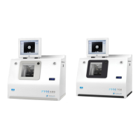
Do you have a question about the Essilor Pro-E 700 edger and is the answer not in the manual?
Guidance on initial setup and basic operations of the Pro-E edger.
Detailed diagrams illustrating the edger's components and connectors.
Instructions on powering the edger on/off and using its touch screen and keypads.
Overview of the edger's work interface and initial lens setup procedures.
Procedures for creating standard and customized bevels on lenses.
Steps for executing high-base bevels, including screen descriptions and modes.
Detailed guide for creating step bevels, including screen layouts and modes.
Instructions for performing automatic and customized grooving on lenses.
Procedure for applying a flat-edge finish, which is accessible in automatic mode only.
Guidance on performing mixed jobs, including menu screens and configuration.
Instructions for adding or modifying drillings on a job, including automatic and customized modes.
Procedure for activating or deactivating the polishing function for lenses.
Explanation of chamfering (counter-bevel) to remove sharp lens edges.
Steps for fine-tuning lens edges after the initial edging cycle.
Procedure for applying a 'Super Chamfer' finish, recommended for specific frame types.
Instructions for performing Chemistrie job, including preparing and cutting lenses.
Guide to performing Half Jacket jobs, including trajectory outlining and shape modification.
Procedures for performing engravings, including motif selection and preparation.
Instructions for creating custom shapes using the M'Eye Touch feature.
Description of the drilling screen and its work area colors and symbols.
Procedures for creating, dimensioning, and adjusting drilling points on a lens.
Settings for edger configuration: time, date, language, connections, and screensaver.
Adjusting edger precision for lens diameter, bevel, groove, drill holes, chamfer, and engraving.
Procedure to restore the edger's factory default settings.
Guide to performing self-diagnosis tests on the edger's job functions.
Instructions for calibrating the touch screen to ensure operational precision.
Checking the wear level of the edger's 'small tools' module components.
Procedures for replacing or cleaning drill bits, mill bits, and other edger tools.
Viewing edger cycle counts, statistics, and technical logs including errors.
Procedures for cleaning edger components and precautions for maintenance.
Technical specifications for the edger, including finishes and materials compatibility.
Recommended installation environment, temperature, and humidity conditions.
Explanation of symbols used on the edger and within the document.
Disclaimer regarding document information, potential for errors, and non-contractual nature.
Compliance statements, FCC rules, and measures for radio frequency interference mitigation.
| Grooving | Yes |
|---|---|
| Drilling | Yes |
| Safety Bevel | Yes |
| Frame Tracing | Automatic |
| Lens Material Compatibility | polycarbonate, high index |
| Lens Diameter Range | 80 mm |
| Bevel Width Adjustment | Yes |
| Bevel Height Adjustment | Yes |
| Power Supply | 50/60 Hz |