The selected eye has an orange frame around it.
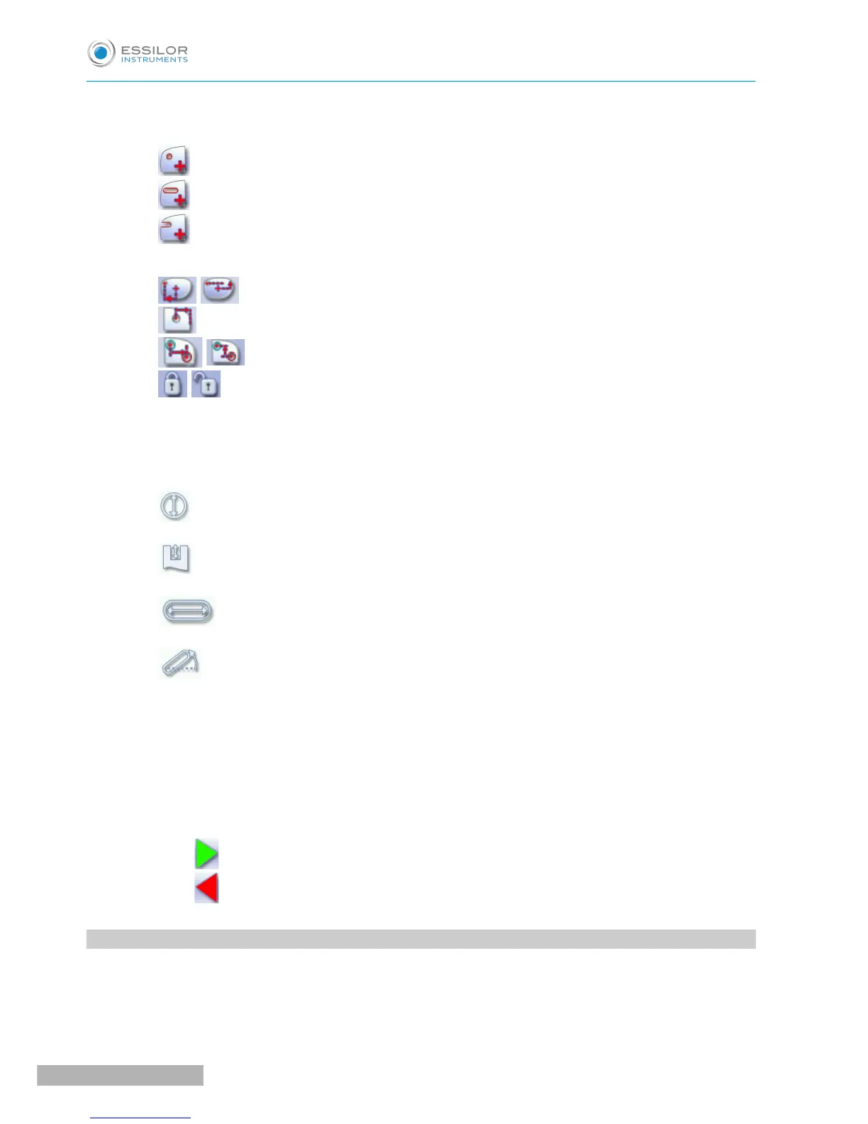
3. Type of drilling
◦ Drill-hole
◦ Slot
◦ Notch
4. Drilling coordinates
◦ X and Y coordinates in relation to the boxing
&
center of the shape.
◦ Distance between the center of the drill-hole entrance point and the edge of the lens.
◦ X and Y coordinates in relation to the reference drilling point.
◦ Freezing of the distance between the drilling point and the edge of the lens.
5. Virtual mouse
Slide the stylus in this area to move the selected drilling points.
6. Drilling point dimensioning
◦ Diameter in mm
◦ default value: 1.40mm
◦ Drilling depth in mm in the case of non-through drilling
◦ default value: 0 (through-drilling)
◦ Length of slot or notch in mm
◦ default value of slot: 3.40mm
◦ Angle of slot or notch in °
◦ default value for right eye: 0° on nasal side, 180° on temporal side
◦ default value for left eye: 180° on nasal side, 0° on temporal side
7. Zoom
8. Symmetrically transfer the drilling points from the nasal to the temporal side or vice versa
9. Modify the selected value
10. Back to the centering screen
◦ Press to save the changes and return to the edging screen.
◦ Press to return to the edging screen without saving the changes.
2. CONFIGURING A DRILLING POINT
This section describes the procedures for the creation and positioning of a drilling point:
• Creating a drilling point (F p.131)
• Dimensioning a drilling point (F p.131)