This chapter describes the procedure for the positioning of drilling points (drill-holes, oblong holes, notches)
on a lens.
• Description of the drilling screen (F p.129)
• Configuring drilling settings (F p.130)
1. MENU SCREEN
From the edging screen:
• press and hold to access the drilling screen.
• make a long click on (when the job already shows drilling).
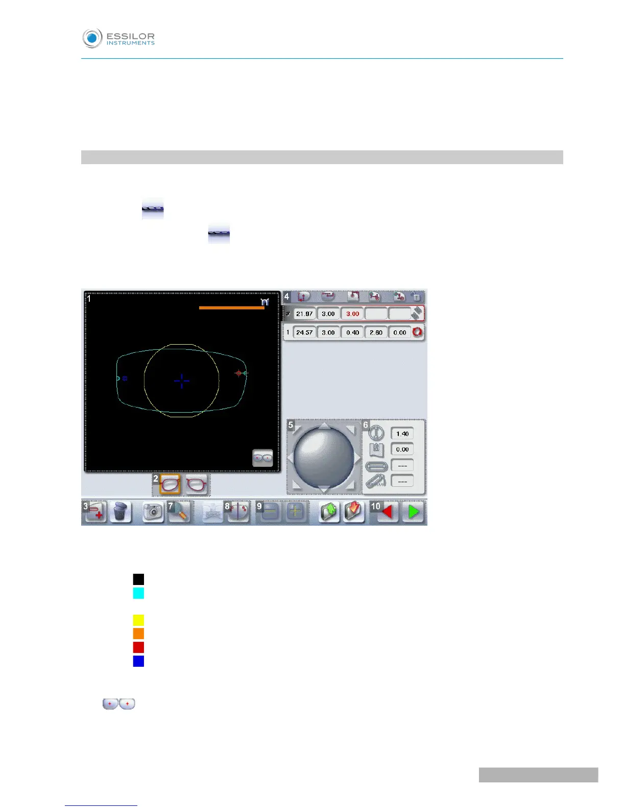
The following screen is displayed:
1. Work area
Colours which may appear on screen:
◦ (green) Current shape (from the shape traced) and associated drilling points
(cyan) Current shape (obtained by symmetry with the shape traced) and associated drilling
points
◦ (yellow) Limit of the no-drill area
◦ (orange) Nasal or temporal side indicator
◦ (red) Selected drilling point
◦ (blue) Reference drilling point (by default, the first one created on each side – nasal and
temporal)
◦ A drilling point with a colour infill indicates non-through drilling
Binocular view
2. Active eye