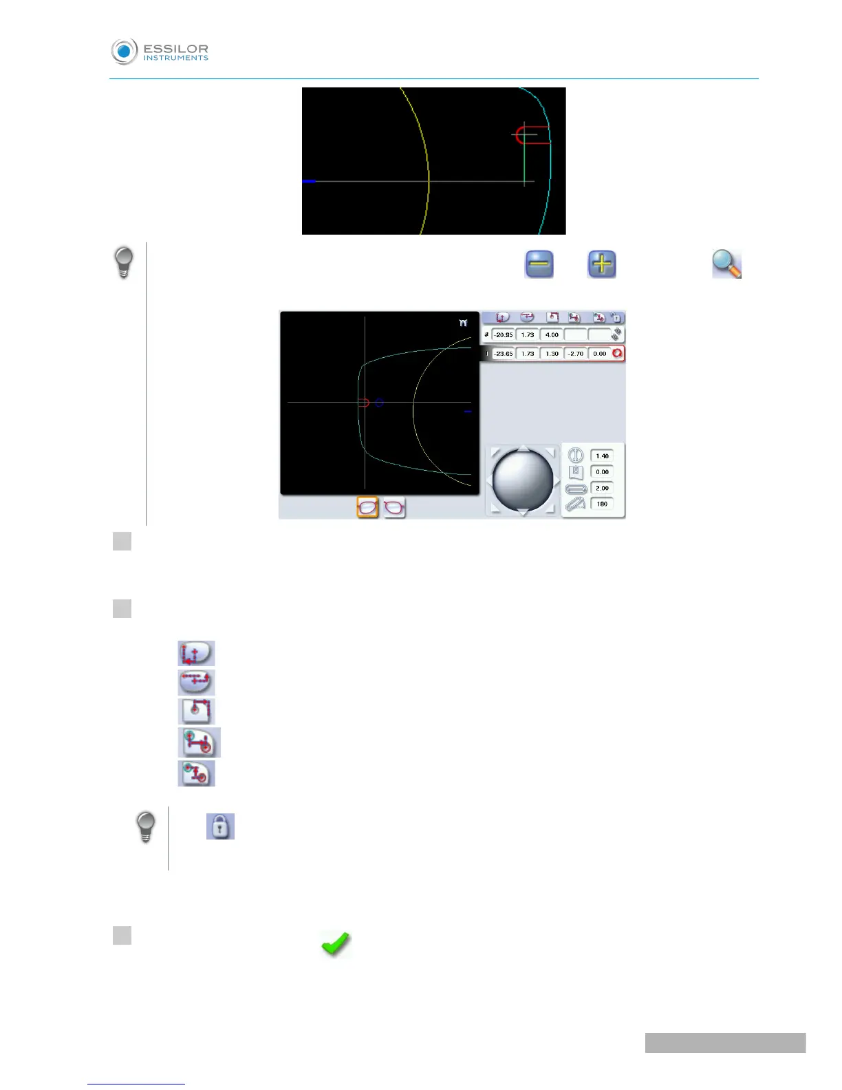
For greater precision, when you use the virtual mouse or the and buttons, press to
zoom in on the selected drilling point: the displacement step is 0.01mm (0.1mm for normal display).
Press on the drill-hole, slot or notch to select it.
The drilling point is displayed in red.
Press a few seconds on the value corresponding to the coordinates to be modified:
• X coordinates
• Y coordinates
• Distance in relation to the edge of the lens.
• X coordinates in relation to the reference drilling point
• Y coordinates in relation to the reference drilling point
Lock the distance in relation to the edge of the lens to adjust only the Y position of the
drilling point.
The numeric keypad is displayed.
Enter the new value and press to confirm.
The drilling coordinates are modified.