Hardware Description18
2.5.2 Back Panel
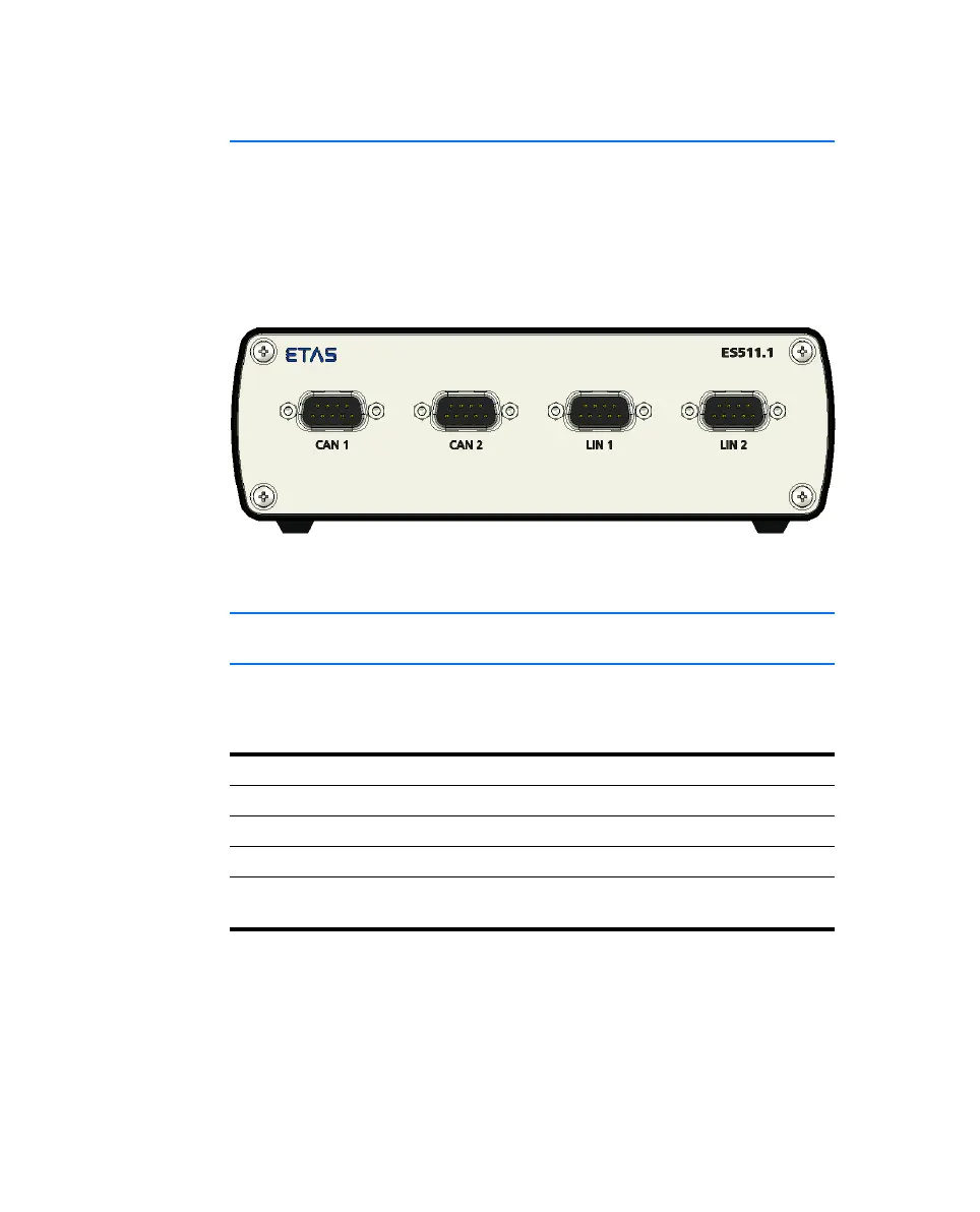
The following ports are on the back of the ES511.1:
• CAN 1 (1 x CAN)
• CAN 2 (1 x CAN)
• LIN 1 (1 x LIN)
• LIN 2 (1 x LIN)
Fig. 2-3 Ports
2.6 LEDs
2.6.1 Overview
The ES511.1 has six LEDs, which indicate the operational, error and synchroni-
zation state of the module, as well as with LEDs which display the functional
state of the assigned Ethernet interface.
LED Display
ON/ER Operational state and possible error states of the module
SYNC Synchronization state of the module
TX Function of the HOST interface
TX Function of the assigned ETHx interface
(one LED each for ETH1, ETH2, ETH3)
Manual.book Seite 18 Montag, 13. Juli 2009 6:24 18