Functional Description 25
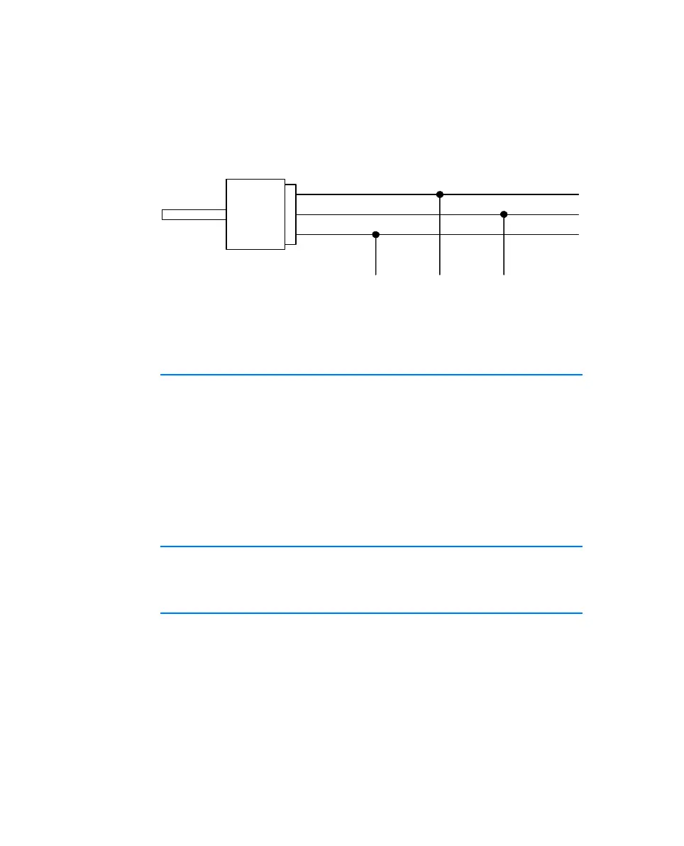
To adhere to the reference level (and thus identical thresholds) at the individual
nodes of the LIN bus, the LIN transceivers (physical layer) of all bus nodes
should be powered with the same voltage. It is recommended that you operate
all nodes of the LIN bus with the external voltage which also powers the other
bus users (LIN_UBATT, see Fig. 3-2 on page 25).
Fig. 3-2 Power Supply at the LIN Bus
The ES511.1 is not designed to power external nodes at the LIN bus.
3.6 FlexRay Interface ("FLEXRAY A", "FLEXRAY B")
The ES512.1 has one FlexRay interface with two channels. One each of the
FlexRay channels is routed to the two 9-pin "FLEXRAY A" and "FLEXRAY B"
connectors (DSUB socket) on the back panel.
"FLEXRAY A" and "FLEXRAY B" are complete independent FlexRay channels
with separated connections. The FlexRay interfaces produce a simple and
direct connection between the ES512.1 and the FlexRay network.
The interfaces are galvanically isolated from each other and from the other
interfaces of the ES512.1
3.6.1 Feature
You can find a list of FlexRay applications supported by the ES512.1 in chapter
5.2.3 on page 38.
3.6.2 Bus Termination Resistor
The FlexRay specification makes it possible to create different bus topologies,
such as a passive bus, passive star or active star.
Each of the topologies requires the relevant bus termination. The FlexRay ter-
mination designated by the ETAS FlexRay specification is 100 Ohm. To support
the creation in FlexRay networks, ETAS provides FlexRay cables with corre-
sponding FlexRay terminations. The termination has to be connected to the
cable or to the connector.
LIN_GND
9
3
7
LIN
D-Sub Connector
9 pin
LIN_UBATT
Manual.book Seite 25 Montag, 13. Juli 2009 6:24 18

 Loading...


