EQT Router User Manual
Page 14 Revision 1.9.1
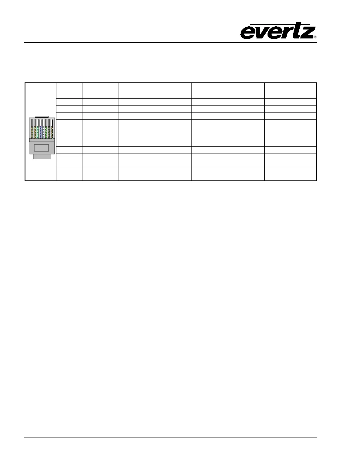
The straight-through RJ-45 cable can be purchased or can be constructed using the pin-out information
in Table 5. A colour coded wiring table is provided in Table 5 for the current RJ-45 standards (AT&T
258A or EIA/TIA 258B colour coding shown). Also refer to the notes following the table for additional
wiring guide information.
Pin
1
Pin # Signal EIA/TIA 568A
AT&T 258A or
EIA/TIA 568B
4 N/A Blue/White or Blue Blue/White or Blue
5 N/A White/Blue White/Blue
7 N/A White/Brown White/Brown
8 N/A Brown/White or Brown Brown/White or Brown
Table 5: Standard RJ-45 Wiring Colour Codes
Note the following cabling information for this wiring guide:
• Only two pairs of wires are used in the 8-pin RJ-45 connector to carry Ethernet signals.
• Even though pins 4, 5, 7 and 8 are not used, it is mandatory that they be present in the cable.
• 10BaseT and 100BaseT use the same pins (a crossover cable made for one will also work with
the other).
• Pairs may be solid colours and not have a stripe.
• Category 5 cable must use Category 5 rated connectors.
The maximum cable run between the router and the supporting hub is 300 ft (90 m). The maximum
combined cable run between any two end points (i.e. router and PC/laptop via network hub) is 675 feet
(205 m).
Devices on the Ethernet network continually monitor the receive data path for activity as a means of
checking that the link is working correctly. When the network is idle, the devices also send a link test
signal to one another to verify link integrity. The EQT rear panel is fitted with two LEDs to monitor the
Ethernet connection.
10/100: This Amber LED is ON when a 100Base-TX link is last detected. The LED is
OFF when a 10Base-T link is last detected (the LINK LED is ON). Upon power-
up the LED is OFF as the last detected rate is not known and therefore defaults
to the 10Base-T state until rate detection is completed.
LN/ACT: This dual purpose Green LED indicates that the EQT has established a valid
linkage to its hub, and whether the EQT is sending or receiving data. This LED
will be ON when the EQT has established a good link to its supporting hub. This
gives you a good indication that the segment is wired correctly. The LED will
BLINK when the EQT is sending or receiving data. The LED will be OFF if there
is no valid connection.
 Loading...