DMTA-20102-01EN, Rev. 7, October 2022
Overview 33
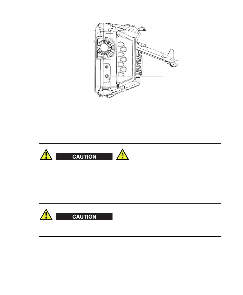
Figure 2-4 Right side panel of the OmniScan X3
2.9 Top Panel
• To reduce the risk of electric shock, avoid touching the inner conductor of the
probe connectors. Up to 350 V can be present on the inner conductor of the UT
connectors, and up to 120 V can be present on the PA connector. The warning
symbol near the PA and UT connectors signals this electric shock risk.
• Reinforced insulation must be provided for the probes connected to the
OmniScan X3 flaw detector.
To avoid the risk of equipment malfunction or damage, use only compatible Evident
probes.
The top panel of the OmniScan X3 contains several types of connectors, as shown in
Figure 2-5 on page 34.
DC power adaptor plug
(flexible cap not shown in
illustration)
 Loading...