DMTA-20102-01EN, Rev. 7, October 2022
Chapter 564
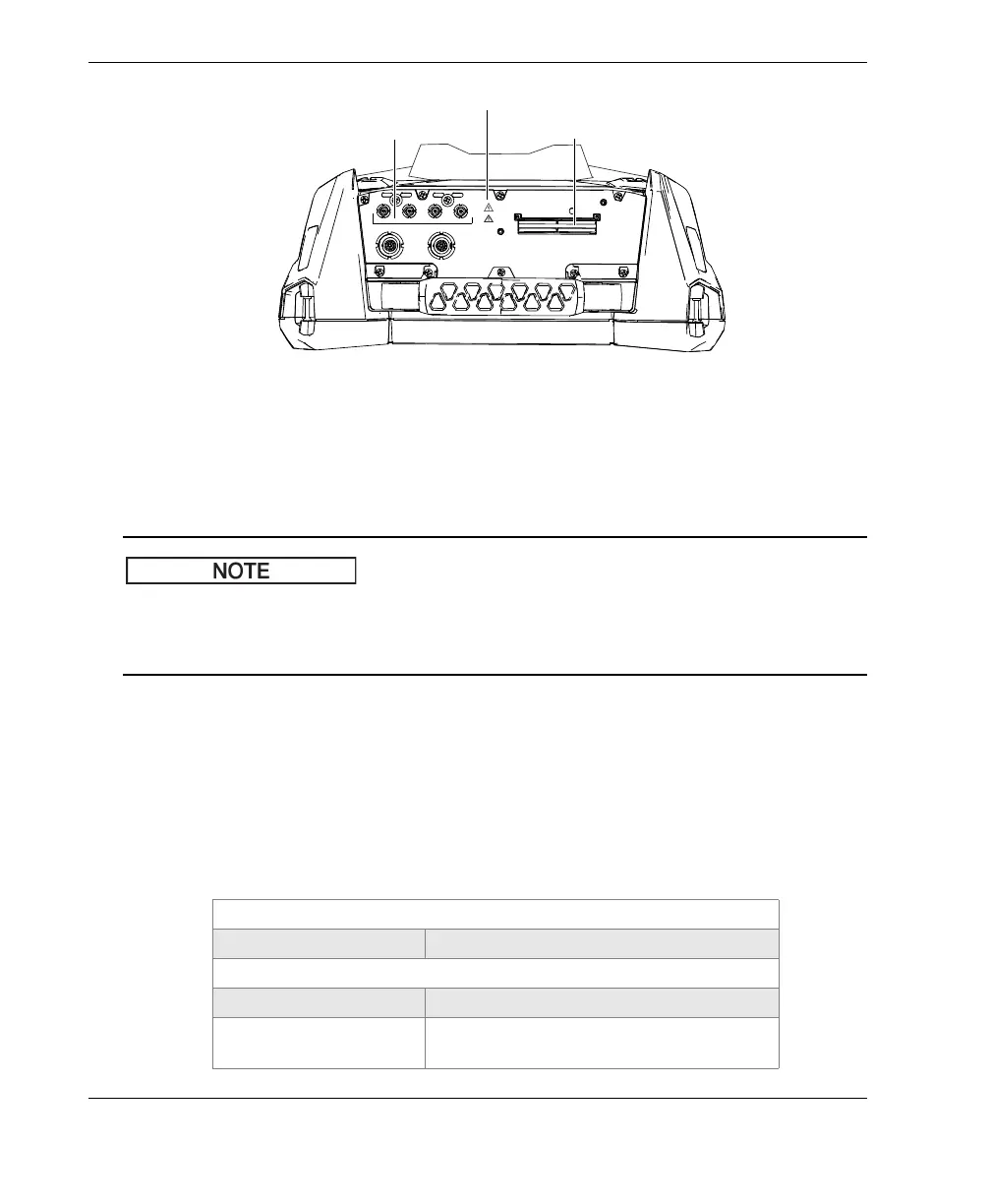
Figure 5-1 Acquisition connectors
When the UT channel is the only channel used, place the PA connector cap over the
PA connector to protect it against dirt and water.
Before using a phased array probe that is not equipped with a latching PA connector
(shown in Figure 2-6 on page 35), remove the anchor base, which is secured by two
screws.
5.2.1 Acoustic Specifications
This section details the acoustic specifications of the pulser, receiver, and beam
formation, for both UT and PA modes (Table 6 on page 64 and Table 7 on page 65).
Table 6 Acoustic specifications—UT channel using UT connector
Certification
Calibration certification ISO 22232
Pulser
Voltage 85 V, 155 V, and 295 V
Pulse width Adjustable from 30 ns to 1000 ns; resolution
of 2.5 ns
Warning symbols
PA connector
UT connectors
 Loading...