DMTA-20102-01EN, Rev. 7, October 2022
Chapter 672
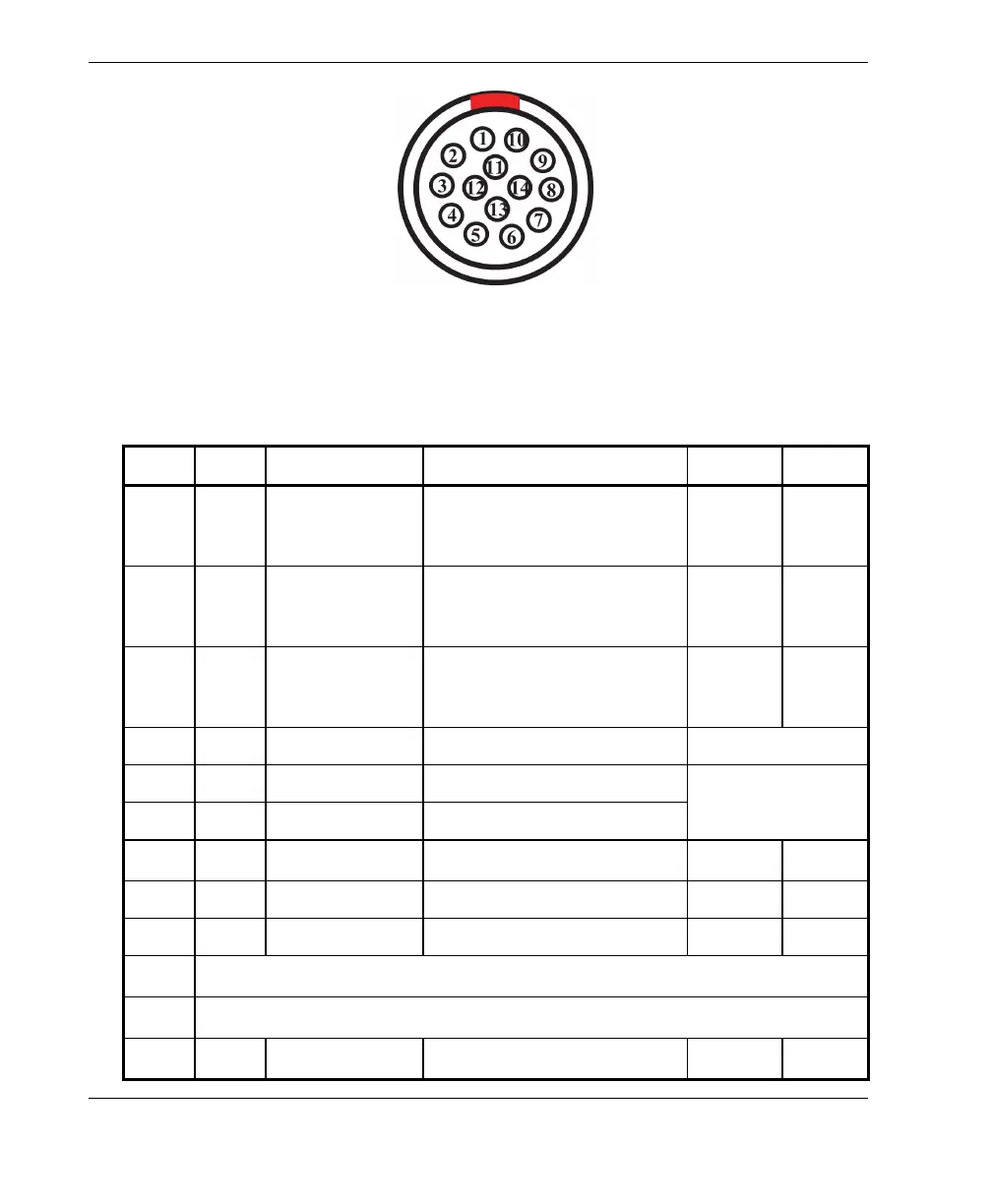
Figure 6-2 Alarm and I/O LEMO connector (contact view)
Table 11 Pinout for the Alarm and I/O connector
Pin I/O Signal Description Current Level
1 Out AL1 Alarm output 1. Disabled on
reset, and is at 0 V. When
active, it is at 5 V.
±20 mA TTL
2 Out AL2 Alarm output 2. Disabled on
reset, and is at 0 V. When
active, it is at 5 V.
±20 mA TTL
3 Out AL3 Alarm output 3. Disabled on
reset, and is at 0 V. When
active, it is at 5 V.
±20 mA TTL
4 Out HP_OUT Analog headphone output 50 mW
5 Out AUD_OUT+ Analog audio output +
600 mW
6OutAUD_OUT− Analog audio output −
7 Out 5 V 5 V external power supply
1A
a
5V
8 Out DOUT4 Digital output 4 ±20 mA TTL
9 Out DOUT5 Digital output 5 ±20 mA TTL
10
NC
b
11
NC
12 –
NU
c
–––
 Loading...