DMTA-20102-01EN, Rev. 7, October 2022
Chapter 234
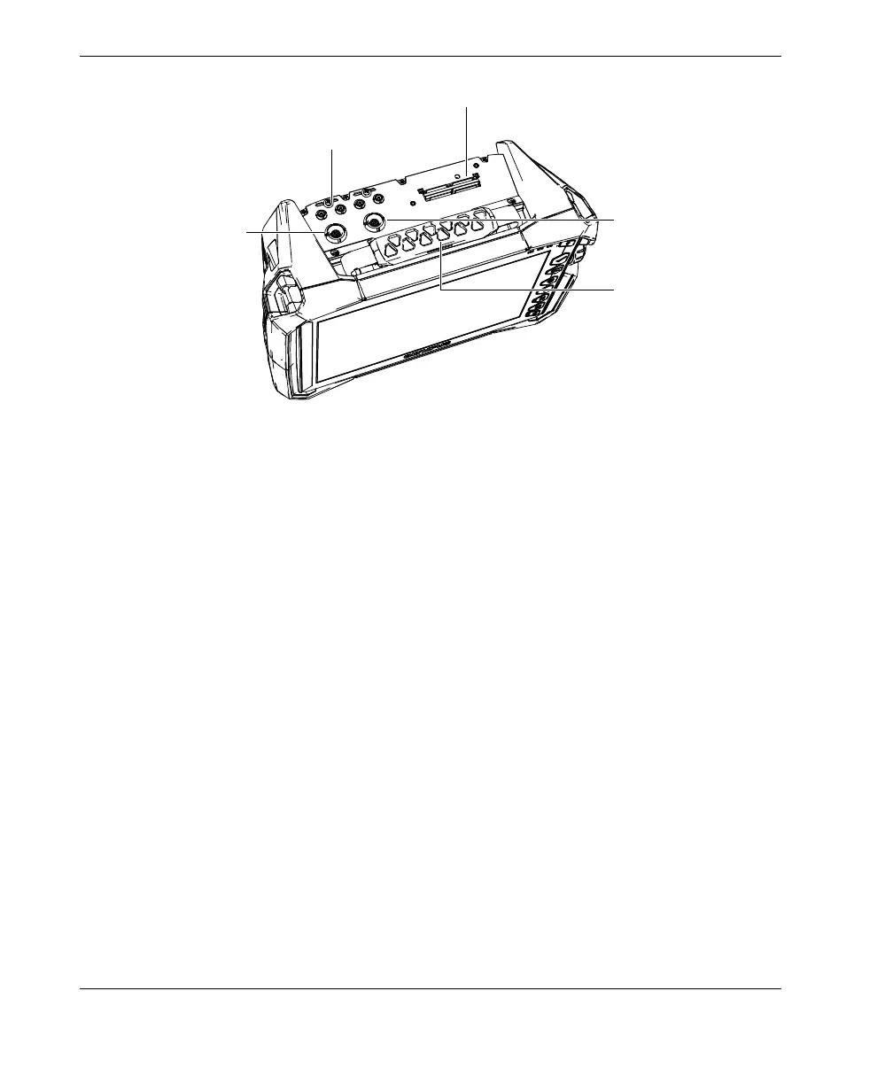
Figure 2-5 Top panel of the OmniScan X3
UT transmission and reception connector: P1 and P2
LEMO connector used for the transmission of ultrasonic signals when using the
pitch-catch inspection technique. When in pulse/echo P1 and P2 are used to
transmit and receive ultrasonic signals.
UT reception connector: R1 and R2
LEMO connector used for the reception of ultrasonic signals when using the
pitch-catch inspection technique.
Alarm and I/O connector
LEMO connector used to connect an external alarm or transmit input and output
signals for other external devices.
Scanner encoder connector
LEMO connector used to connect a scanner equipped with an encoder or transmit
input and output signals for other external devices.
PA connector
Used to connect a phased array probe and probe splitter or adaptor.
Figure 2-6 on page 35 shows the connectors that are compatible with those listed
above.
Alarm and I/O
connector
UT connectors:
P1 / R1, plus P2 / R2 (four total)
PA connector
Scanner encoder
connector
Note: the connector caps are
not shown in the image. You
should normally cover unused
connectors.
Handle for carrying the
OmniScan X3 flaw
detector