Design and function
Welding data display
099-000121-EW501
29.06.2015
5.8 Welding data display
The following welding parameters can be displayed before (nominal values), during (actual values) or
after welding (hold values):
Before welding
(nominal values)
During welding
(actual values)
After welding
(hold values)
When the settings are changed (e.g. welding current) after welding when the hold values are displayed,
the display will be switched to the relevant nominal values.
If the "Program number" signal light is on in addition to the "Material thickness" signal light, the user is in
program mode (programs 1-15, , - See 5.11 Welding programs chapter).
If the "JOB-number" signal light is on in addition to the "Material thickness" light, the user is in a JOB in
the free memory (JOB 128 to 256, - See 5.12.2 Creating a new JOB in the memory or copying a JOB
chapter).
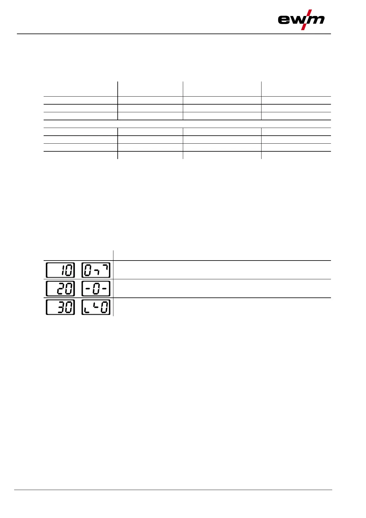
5.8.1 Welding parameter setting
During the welding parameter setting process, the parameter value being set is displayed on the left-hand
display. The right-hand display shows the “Factory setting” or a variation of it upwards or downwards.
Displays, e.g. when setting the ignition current, and their meanings:
Meaning of the symbols shown in the right-hand display
Increase parameter value To restore the factory settings.
Factory setting Parameter value is on the optimum setting
Reduce parameter value To restore the factory settings.