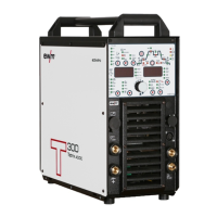
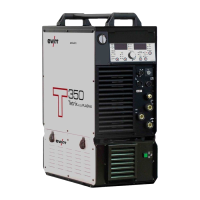
Design and function
Interfaces for automation
099-000121-EW501
29.06.2015
5.15 Interfaces for automation
Damage to the machine due to improper connection!
Unsuitable control leads or incorrect connection of input and output signals can cause
damage to the machine.
• Only use shielded control leads!
• If the machine is to be operated with control voltages connection via suitable isolation
amplifiers is required!
• To control the main or secondary current via control voltages, the relevant inputs must be
enabled (see specification for activation of control voltage).
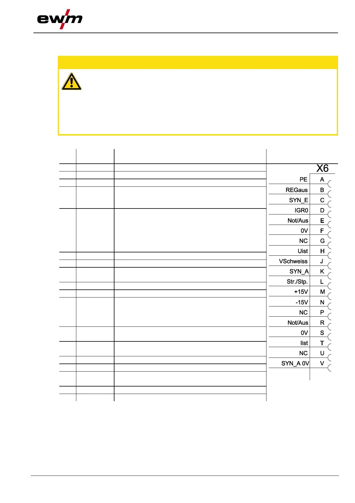
5.15.1 TIG interface for mechanised welding
PE Connection for cable screen
REGaus For servicing purposes only
SYN_E Synchronisation for master/slave operation
IGRO Current flows signal I>0 (maximum load
20mA / 15V)
0V = welding current flowing
Not/Aus Emergency stop for higher level shut-down
of the power source.
To use this function, jumper 1 must be
unplugged on PCB T320/1 in the welding
machine. Contact open welding current
off
Uist Actual welding voltage, measured on pin F,
0-10V (0V = 0V, 10V = 100V)
Vschweiss Reserved for special purposes
SYN_A Synchronisation for master/slave operation
Str/Stp Start / stop welding current, same as torch
trigger.
Only available in non-latched operating
mode. +15V = start, 0V stop
+15V Voltage supply
+15V, max. 75mA
-15V Voltage supply
-15V, max. 25mA
Iist Actual welding current, measured on pin F;
0-10V (0V = 0A, 10V = 1000A)
SYN_A 0V Synchronisation for master/slave operation