Design and function
TIG welding
099-000121-EW501
29.06.2015
If fitted:
• Lock connecting nipples of the cooling water tubes into the corresponding quick connect couplings:
Return line red to quick connect coupling, red (coolant return) and
supply line blue to quick connect coupling, blue (coolant supply).
Please note the relevant documentation of the accessory components.
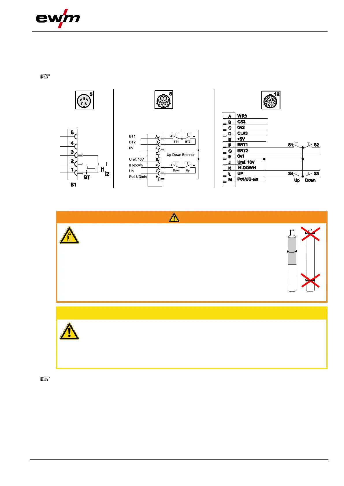
5.9.1.1 Torch connection options and pin assignments
Figure 5-8
5.9.2 Shielding gas supply (shielding gas cylinder for welding machine)
Risk of injury due to improper handling of shielding gas cylinders!
Improper handling and insufficient securing of shielding gas cylinders
can cause serious injuries!
• The fastening elements must tightly enclose the shielding gas cylinder!
• Attach the fastening elements within the upper half of the shielding gas
cylinder!
• Do not attach any element to the shielding gas cylinder valve!
• Observe the instructions from the gas manufacturer and any relevant
regulations concerning the use of compressed air!
• Avoid heating the shielding gas cylinder!
Faults in the shielding gas supply.
An unhindered shielding gas supply from the shielding gas cylinder to the welding
torch is a fundamental requirement for optimum welding results. In addition, a blocked
shielding gas supply may result in the welding torch being destroyed.
• Always re-fit the yellow protective cap when not using the shielding gas connection.
• All shielding gas connections must be gas tight.
Before connecting the pressure regulator to the gas cylinder, open the cylinder valve briefly to
expel any dirt.
5.9.2.1 Connecting the shielding gas supply
• Place the shielding gas cylinder into the relevant cylinder bracket.
• Secure the shielding gas cylinder using a securing chain.