Operation
1. Stop the mac hine and mo v e the dri v e lev ers to
the neutral position.
2. Diseng ag e the PTO .
3. Eng ag e the park brak e .
4. Stop the engine , remo v e the k ey and w ait for all
mo ving par ts to stop .
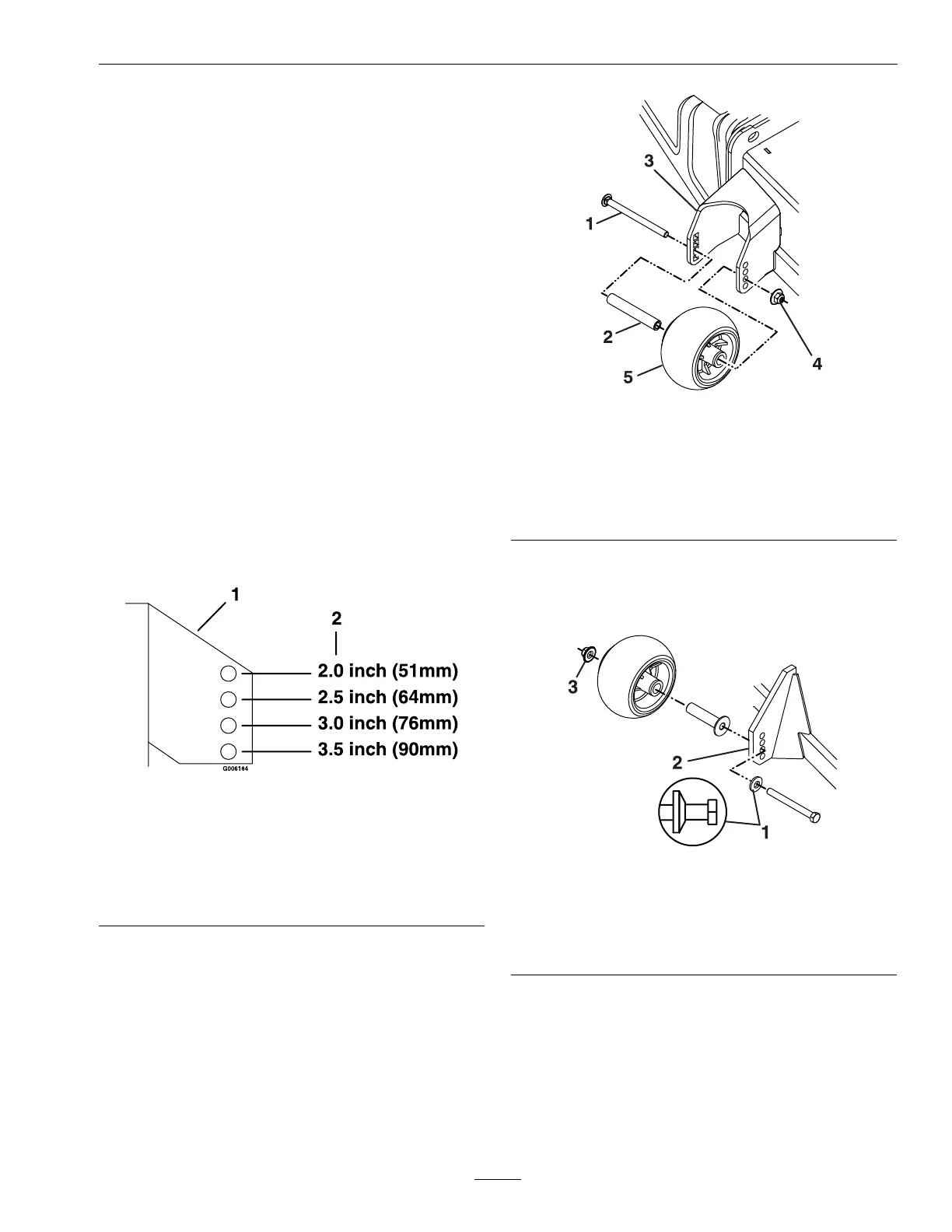
5. After adjusting the height of cut, adjust the
anti-scalp rollers b y remo ving the nyloc n ut,
spacer , and bolt.
6. Adjust anti-scalp rollers for nor mal operating
conditions . Place rollers in one of the positions
sho wn in Figure 12 . R ollers will maintain 3/4
inc hes (19 mm) clearance to the g round to
minimize g ouging and roller w ear or damag e .
Note: F or Maximum Deck F lotation , place
rollers one hole position lo w er . R ollers should
maintain 1/4 inc h (6.35 mm) clearance to g round.
Do Not adjust rollers to suppor t the dec k.
Note: R oller ma y need to be remo v ed when
mo wing at 1 inc h (25 mm).
g006184
Figure 12
For cutting heights above 3.5 inches (38 mm) use the
bottom hole. The rollers will still be ef fective against
scalping.
1. Anti-scalp roller
mounting bracket
2. Cutting height
7. F or S-Series: Be sure roller bolts are installed
with the spring disc w asher betw een head of the
bolt and mounting brac k et.
8. R einstall the mounting hardw are:
• F or X-Series:
the 3/8-16 nyloc n ut to 27-33 ft-lb (37-45
N-m) ( Figure 13 ).
g433945
Figure 13
1. 3/8-16 x 5 inch bolt 4. 3/8 nyloc- to 27-33 ft-lb
(37-45 N-m)
2. Spacer
5. Anti-scalp roller
3. Front right anti-scalp
bracket shown
• F or S-Series:
the 3/8-16 nyloc n ut to 50–55 ft-lb (68-75
N-m) ( Figure 14 ).
g345136
Figure 14
1. 3/8-16 x 3 3/4 Grade 8
bolt
3. Front right anti-scalp
bracket shown
2. Spring disc washer
(cone towards bolt )
4. 3/8 nyloc- to 50–55 ft-lb
(68-75 N-m)
29
 Loading...