• 40G-QSFP-ESR4 (with fiber breakout cables and additional 10GbE optics).
For 4x 25GbE breakout:
• 100G-QSFP-4SFP-P-XXX
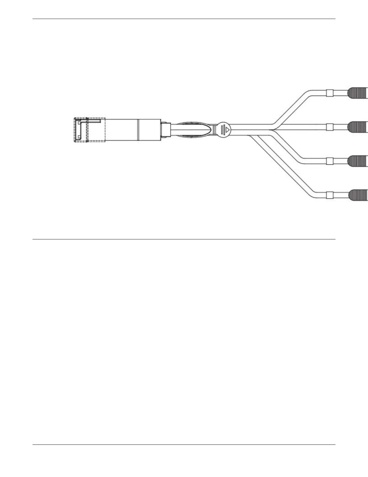
Figure 39: QSFP+ to 4 SFP+ (4 x 10 GbE) direct-attach copper breakout cable
Verifying transceiver operation
To verify operation of a transceiver, view the LEDs on the transceiver. To find the LED locations on the
interface modules, refer to LED activity interpretation on page 74. After you have connected and
configured the ports for Ethernet connectivity and connected the cable to another active port, the LED
becomes solid green. When trac is detected on the port, the light becomes blinking green.
You can also enter the show interface status and show ip interface brief commands
to verify proper transceiver operation.
Transceivers and Cables
Verifying transceiver operation
ExtremeRouting SLX 9640 Hardware Installation Guide 73
 Loading...