Monitoring the Device
Monitoring Overview on page 74
LED activity interpretation on page 74
LED indicators on page 75
Monitoring Overview
The Extreme device is engineered for reliability and requires no routine operational steps or
maintenance. You can monitor the device by paying attention to the following information:
• The LEDs showing the status of system components
• A description of the operations that the device performs when you power it on
The following commands can be especially helpful in monitoring the health status of various device
components. For details about these commands, refer to the Extreme SLX-OS Monitoring Configuration
Guide for the SLX 9640 device.
• show chassis
• show system
• show slots
• show linecard
• show environment fan
• show environment power
• show environment sensor
• show environment temp
LED activity interpretation
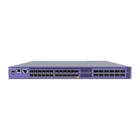
The SLX 9640 switch router has the following LEDs on the front panel:
• One power single-color status LED (green)
• One status bicolor status LED (green and amber)
• One fan bicolor status LED (green and amber)
• One PSU bicolor status LED (green and amber)
The figure below shows the LEDs on the SLX 9640 switch router front panel.
74
ExtremeRouting SLX 9640 Hardware Installation Guide
 Loading...