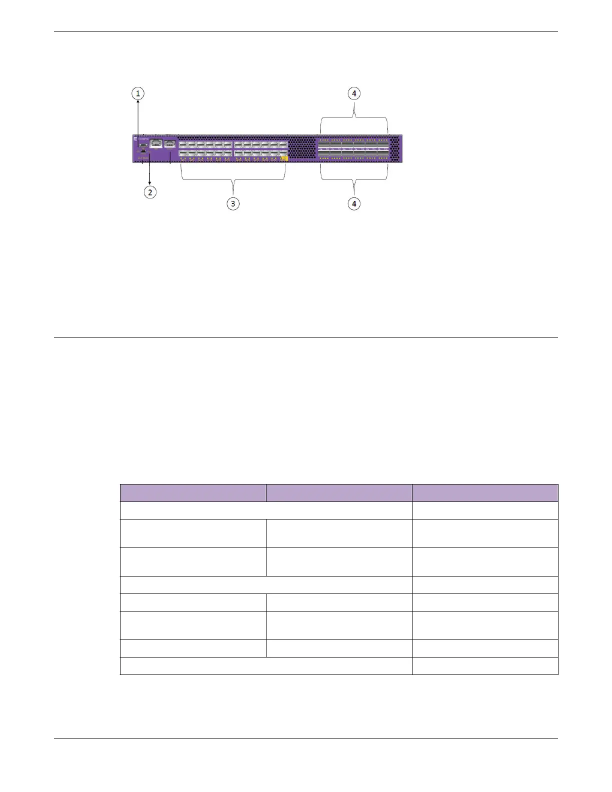
Figure 40: SLX 9640 switch router LEDs
1. Power LED
2. Status LED
3. Status Port LEDs SFP+ ports (1G/10G) ports
4. Status LEDs for QSFP ports
LED indicators
The SLX 9640 device LED indicators are as follows:
• The Power/Status LEDs are visible to the front panel
• The Ethernet LEDs are integrated with the RJ45 connector
• The Power supply LEDs are integrated with the PSU
• The 10G and 100G Port LEDs are surface mount types. They are visible to the front panel
The Table below shows the LEDs Indications on the SLX 9640 device.
Table 17: SLX 9640 device LED Indications
LED Function/state Meaning Possible cause
Power
O No power Some Power rails are dropping
below specification
Green Valid power. All monitored
voltages are nominal
Status (bicolor)
Blinking Amber-Green Attention TBD by SW
Amber Fault/ initial state This LED shall be lit during the
reboot
Green Board is operational
1G Ethernet Status
Monitoring the Device LED indicators
ExtremeRouting SLX 9640 Hardware Installation Guide 75
 Loading...