Digital Brushless AC servo drive system - Ref.0707 MCS- 63/92
Function: Monitors the input voltage through analog input 1 (pins 5 - 6
of X1). It's display is in volts.
Function: Monitors the input voltage through analog input 2 (pin 7 of
X1). It's display is in volts.
Function: Contains the value of the auxiliary analog command (pin 7 of
X1; usually current command) after being affected by CP10
and CP11. It must never exceed the value of the maximum
current of the unit.
Valid values: - 50.00 ... + 50.00 Arms.
Default value: 0.
Function: This variable reflects the status of the programmable digital
input at pins 8 - 9 of connector X2. The status of this variable
is affected by IP6.
Valid values: 0 (by default) and 1.
IV1 BASIC, RO AnalogInput1
IV2 USER, RO AnalogInput2
IV3 USER, RO CurrentCommandAfterScaling
IV10 USER, RO DigitalInputs
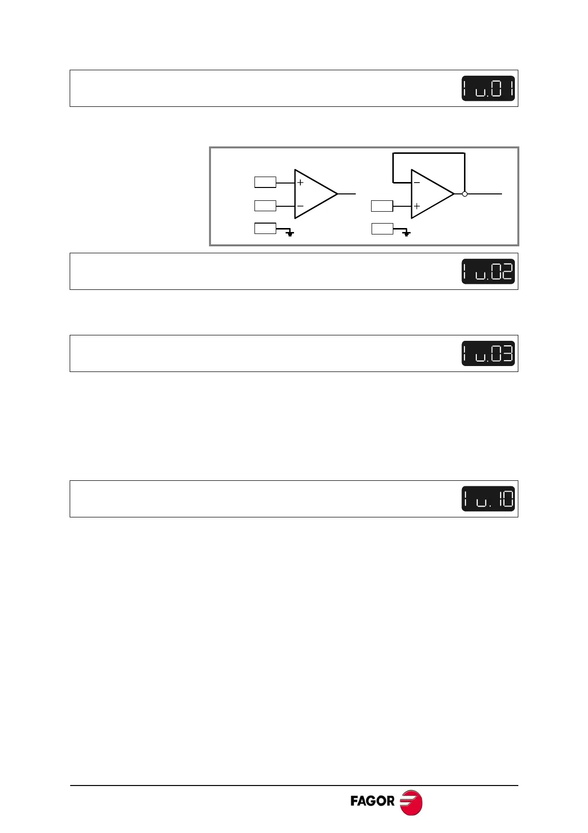
VEL +
VEL -
IV1
16 Bit
IV2
PROG_
ANALOG_INPUT
X1.5
X1.6
X1.4
X1.7
X1.4
10 Bit
 Loading...
