98
(MT12 - Gb2004)
I
NTERCOMS *
V
IDEOINTERCOMS *
T
ELECOMMUNICATION
coax
VIDEO INTERCOM SYSTEM CONNECTED TO ONE EXTERNAL DOOR STATION
Diagram ref. Q.ty Article Description
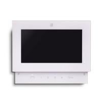
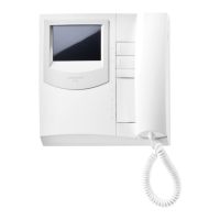
VC ... PT 5160 + WB 5100 Videointercom FLAT + wall bracket
PT 5660 + WB 5600 + 1283 Videointercom + wall bracket + back box
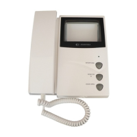
PT 5860 + WB 5600 Videointercom reflex + wall bracket
PV 1260 + WB1200 + 1283 Videointercom + wall bracket + back box
PV 2160 + WB 2100 Videointercom FLAT + wall bracket
DV ... DV2-4 Video distributor
AL 1 1281 Power supply
TR 1 1382 Timer
PA 1 ** Door release button (optional)
SE 1 ** Electric door lock (12Vac-1A)
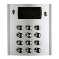
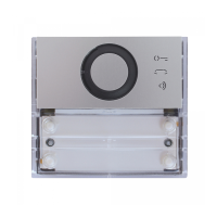
External door station
Mody series (for the composition see pages 82÷85)
1 row 2 row
UR 1 MD41 MD41 Camera module
PB ... MD72-73-74 MD72-73-74 Back boxes and module frames
1 MD10-11-12 MD10-122-124 Modules for electric door speaker
... MD21 ÷ 24 MD222 ÷ 228 Button modules
... MD20 - 50 MD20 - 50 Blank and info modules
1 MD82 ÷ 812 MD82 ÷ 812 Hood covers
1 MD92 ÷ 912* MD92 ÷ 912* Rain shelters
PE 1 MD30 MD30 Electric door speaker (amplifier)
Matrix series (for the composition see pages 88÷89)
UR 1 MA42-43 Camera modules with integrated audio amplifier
PB ... MA20-22-24 Blank and button modules
... MA61-62-63 Front frames
... MA71-72-73 Back boxes and module frames
... Refers to number of users.
* The rain shelter is used in the place of the back box and hood cover.
** Articles not supplied by ACI Farfisa.
Working instructions. See page 94.
Notes
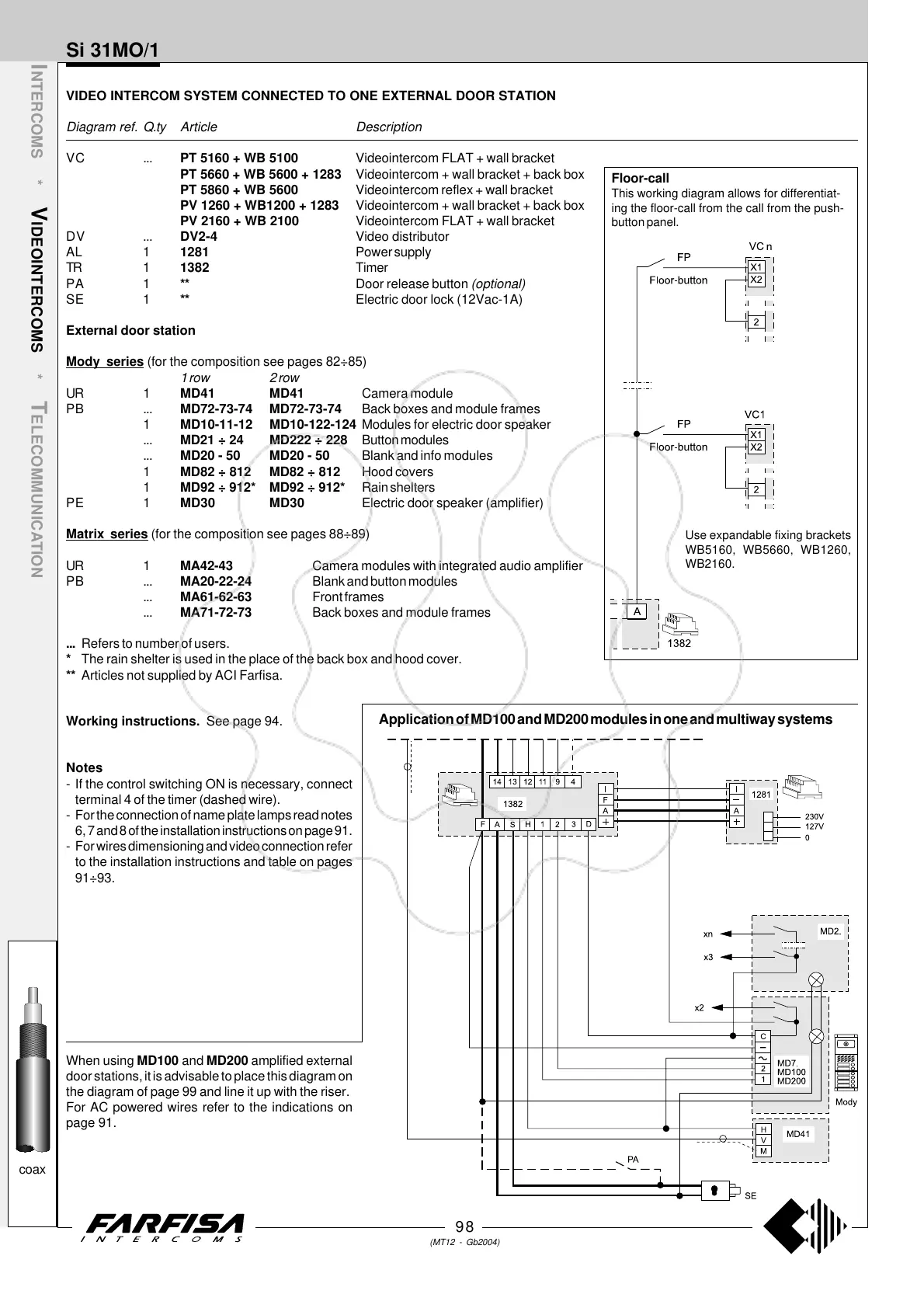
- If the control switching ON is necessary, connect
terminal 4 of the timer (dashed wire).
- For the connection of name plate lamps read notes
6, 7 and 8 of the installation instructions on page 91.
- For wires dimensioning and video connection refer
to the installation instructions and table on pages
91÷93.
Application of MD100 and MD200 modules in one and multiway systems
Si 31MO/1
Use expandable fixing brackets
WB5160, WB5660, WB1260,
WB2160.
Floor-call
This working diagram allows for differentiat-
ing the floor-call from the call from the push-
button panel.
When using MD100 and MD200 amplified external
door stations, it is advisable to place this diagram on
the diagram of page 99 and line it up with the riser.
For AC powered wires refer to the indications on
page 91.
 Loading...