54
(MT12 - Gb2004)
Si 135L/5S
I
NTERCOMS *
V
IDEOINTERCOMS *
T
ELECOMMUNICATION
5 INTERCOMMUNICATING INTERCOMS CONNECTED TO 3 EXTERNAL DOOR STATIONS WITH SINGLE CALLS. ELECTRONIC
BELL FOR INTERNAL CALLS.
Q.ty Article Description
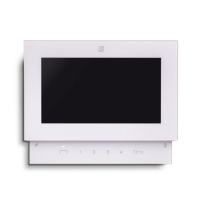
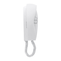
... PT520 Project series modular intercom
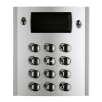
... PT501 Single button unit
... SR40 Electronic bell module
1 PRS226 Power supply-switcher
2 1473 Exchanger
3 PA ** Door release push-button (optional)
3 SE ** Electric door lock (12VAC-1A)
Door station series Mody (for right item set see on pages 12÷15)
1 row 2 row
... MD71÷73 MD71÷73 Module frames with back box
3 MD10-11-12 MD10-122-124 Modules for electric door speaker
... MD21 ÷ 24 MD222 ÷ 228 Button modules
... MD20 - 50 MD20 - 50 Blank and info modules
3 MD81 ÷ 83 MD81 ÷ 83 Hood covers
3 MD91 ÷ 93* MD91 ÷ 93* Rain shelters with module frames
3 MD30 MD30 Electric door speaker (amplifier)
Door station series Matrix (for right item set see on pages 20 and 21)
... MA71÷73 Module frames with back box
3 MA10P-11P-12P Modules with integrated audio amplifier
... MA20-22-24 Blank and button modules
... MA61÷63 Front frames
... Refers to number of users (see table).
* Rain shelters are used instead of back boxes and
hood covers.
** Articles not supplied by ACI Farfisa.
Working instructions
As the basic system described on page 27, with the
following variations:
- The audio functions and door lock opening are auto-
matically switched to the door station which has made
the call and remain in this state until a call from another
entrance is received.
Notes
- For the connection of name-plate lamps, read notes 6
and 7 of the installation instructions on page 26.
- For wires dimensioning refer to the installation recom-
mendations and table on page 26.
- For other types of push-button panels see pages 22 and
23 or the general catalogue.
P
R
O
J
E
C
T
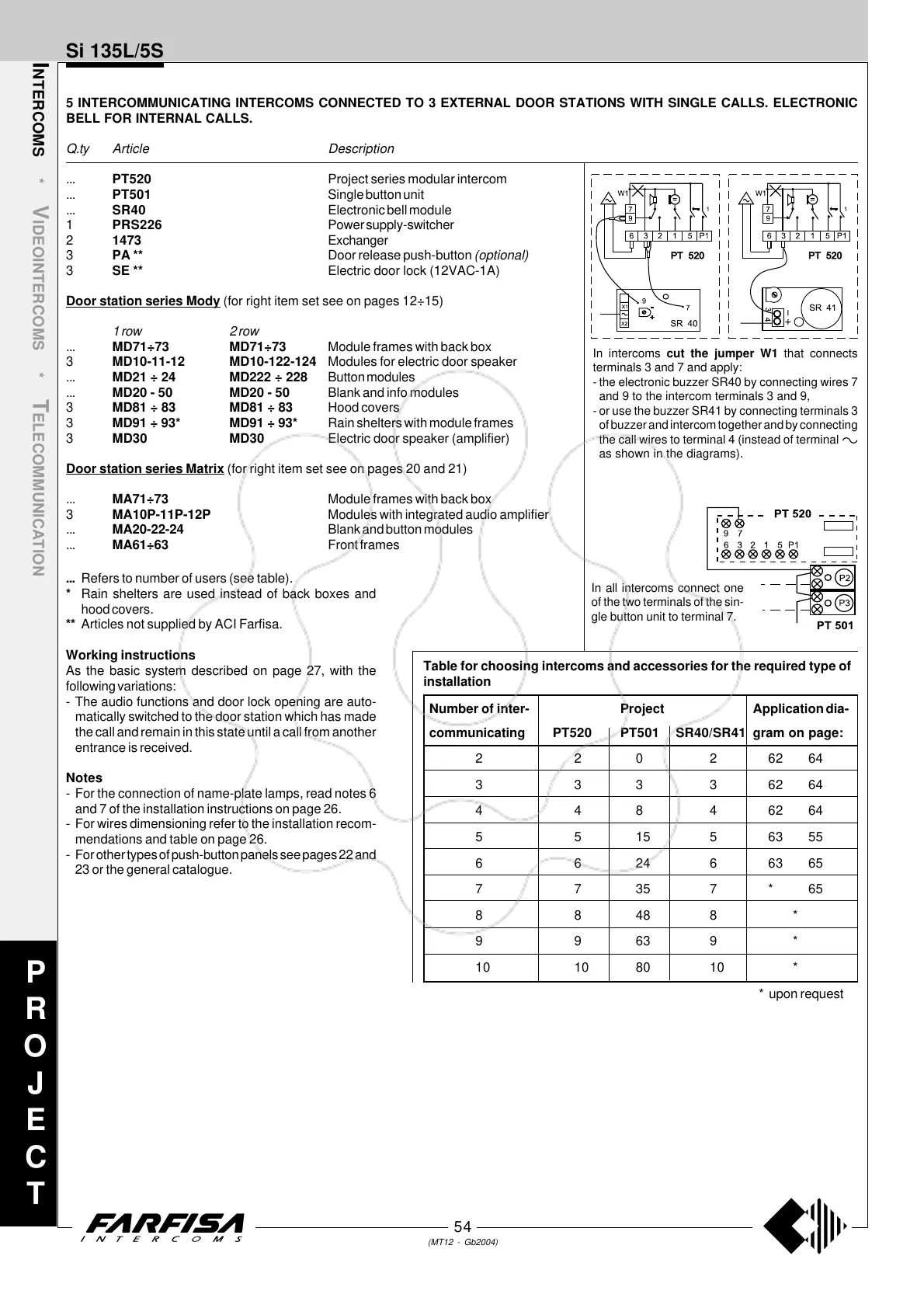
In intercoms cut the jumper W1 that connects
terminals 3 and 7 and apply:
- the electronic buzzer SR40 by connecting wires 7
and 9 to the intercom terminals 3 and 9,
- or use the buzzer SR41 by connecting terminals 3
of buzzer and intercom together and by connecting
the call wires to terminal 4 (instead of terminal
as shown in the diagrams).
In all intercoms connect one
of the two terminals of the sin-
gle button unit to terminal 7.
Number of inter- Project Application dia-
communicating PT520 PT501 SR40/SR41 gram on page:
2 2 0 2 62 64
3 3 3 3 62 64
4 4 8 4 62 64
551556355
662466365
7 7 35 7 * 65
88488*
99639*
10 10 80 10 *
* upon request
Table for choosing intercoms and accessories for the required type of
installation