62
(MT12 - Gb2004)
Application diagrams
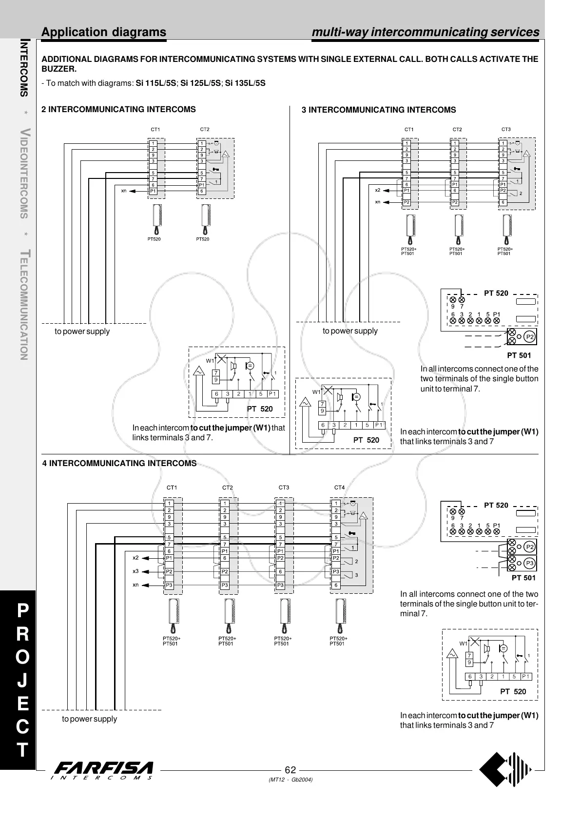
2 INTERCOMMUNICATING INTERCOMS
I
NTERCOMS *
V
IDEOINTERCOMS *
T
ELECOMMUNICATION
3 INTERCOMMUNICATING INTERCOMS
4 INTERCOMMUNICATING INTERCOMS
ADDITIONAL DIAGRAMS FOR INTERCOMMUNICATING SYSTEMS WITH SINGLE EXTERNAL CALL. BOTH CALLS ACTIVATE THE
BUZZER.
- To match with diagrams: Si 115L/5S; Si 125L/5S; Si 135L/5S
to power supply
to power supply
to power supply
P
R
O
J
E
C
T
In all intercoms connect one of the
two terminals of the single button
unit to terminal 7.
In all intercoms connect one of the two
terminals of the single button unit to ter-
minal 7.
In each intercom to cut the jumper (W1) that
links terminals 3 and 7.
W1
1
PT 520
In each intercom to cut the jumper (W1)
that links terminals 3 and 7
W1
1
PT 520
In each intercom to cut the jumper (W1)
that links terminals 3 and 7
W1
1
PT 520
multi-way intercommunicating services