48
(MT12 - Gb2004)
Si 111L/5M
I
NTERCOMS *
V
IDEOINTERCOMS *
T
ELECOMMUNICATION
5 INTERCOMMUNICATING INTERCOMS CONNECTED TO 1 EXTERNAL DOOR STATION WITH COMMON CALL. ELECTRONIC
BELL FOR INTERNAL CALLS.
Q.ty Article Description
... PT520 Project series modular intercom
... PT501 Single button unit
... SR40 Electronic bell module
1 PRS226 Power supply-switcher
1 PA ** Door release push-button (optional)
1 SE ** Electric door lock (12VAC-1A)
Door station series Mody
1 MD71 Module frames with back box
1 MD11 Module for electric door speaker
1 MD81 Hood cover
1 MD91* Rain shelter with module frames
1 MD30 Electric door speaker (amplifier)
Door station series Matrix
1 MA71 Module frames with back box
1 MA11P Module with integrated audio amplifier
1 MA61 Front frame
... Refers to number of users (see table).
* Rain shelters are used instead of back boxes and hood
covers.
** Articles not supplied by ACI Farfisa.
Working instructions. See page 27
.
Notes
- For the connection of name-plate lamps, read notes 6 and
7 of the installation instructions on page 26.
- For wires dimensioning refer to the installation recommen-
dations and table on page 26.
- For other types of push-button panels see pages 22 and 23
or the general catalogue.
Application diagram
When using MD100, MD200, RP200, UP12 and UP200 amplified
external door stations (RP and UP series for two-way systems only)
place this diagram on the diagram on page 49 and line it up with the
riser.
Warning.
- In the external door stations RP200 cut the jumper W1.
- In the external door stations UP do not connect the yellow wire and
insulate it.
- For alternate current wires refer to note 6 of the installation instruc-
tions on page 26.
P
R
O
J
E
C
T
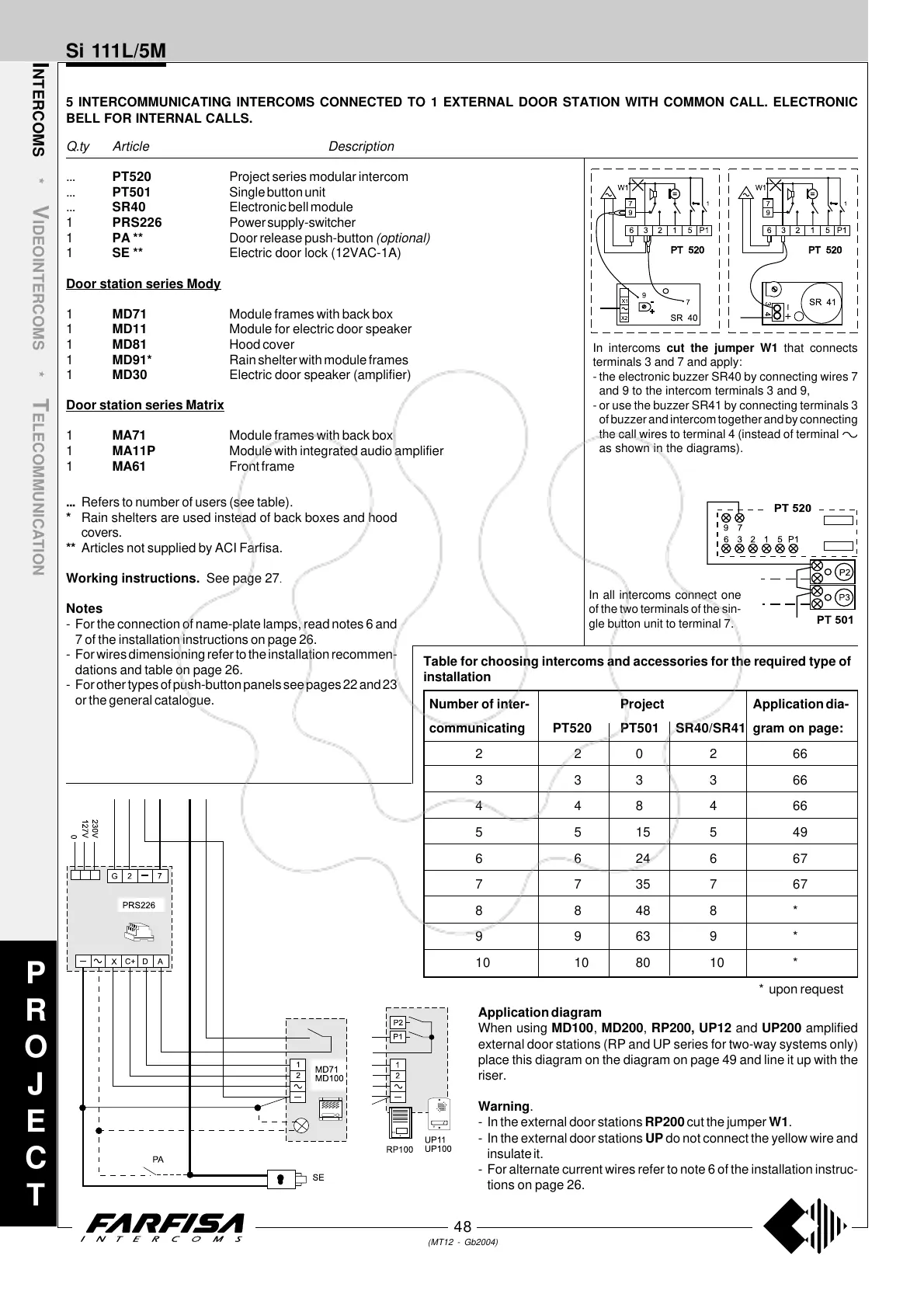
In intercoms cut the jumper W1 that connects
terminals 3 and 7 and apply:
- the electronic buzzer SR40 by connecting wires 7
and 9 to the intercom terminals 3 and 9,
- or use the buzzer SR41 by connecting terminals 3
of buzzer and intercom together and by connecting
the call wires to terminal 4 (instead of terminal
as shown in the diagrams).
In all intercoms connect one
of the two terminals of the sin-
gle button unit to terminal 7.
Number of inter- Project Application dia-
communicating PT520 PT501 SR40/SR41 gram on page:
220266
333366
448466
5515549
6624667
7735767
88488*
99639*
10 10 80 10 *
* upon request
Table for choosing intercoms and accessories for the required type of
installation