173
(MT12 - Gb2004)
I
NTERCOMS *
VIDEO INTERCOMS *
TELECOMMUNICATION
F
A
R
T
E
L
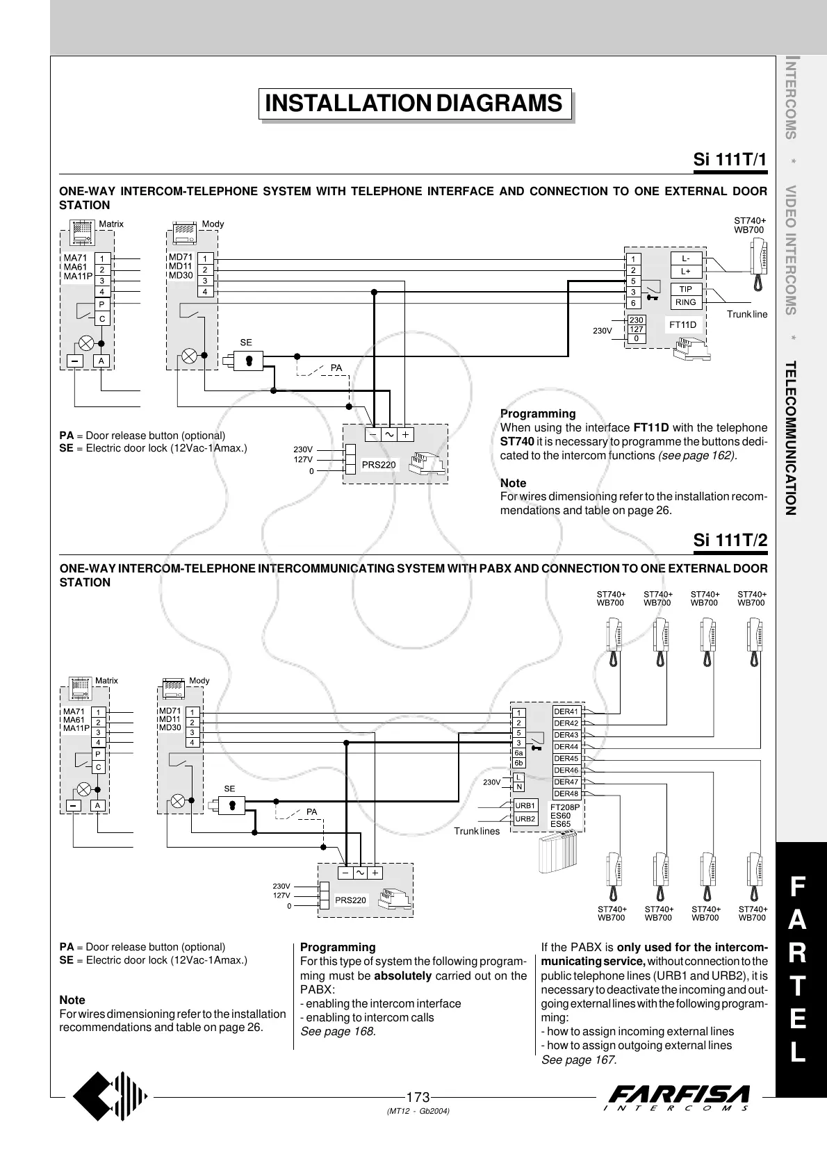
INSTALLATION DIAGRAMS
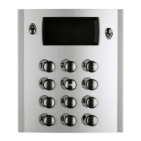
ONE-WAY INTERCOM-TELEPHONE SYSTEM WITH TELEPHONE INTERFACE AND CONNECTION TO ONE EXTERNAL DOOR
STATION
ONE-WAY INTERCOM-TELEPHONE INTERCOMMUNICATING SYSTEM WITH PABX AND CONNECTION TO ONE EXTERNAL DOOR
STATION
Si 111T/2
Si 111T/1
PA = Door release button (optional)
SE = Electric door lock (12Vac-1Amax.)
Programming
For this type of system the following program-
ming must be absolutely carried out on the
PABX:
- enabling the intercom interface
- enabling to intercom calls
See page 168.
If the PABX is only used for the intercom-
municating service, without connection to the
public telephone lines (URB1 and URB2), it is
necessary to deactivate the incoming and out-
going external lines with the following program-
ming:
- how to assign incoming external lines
- how to assign outgoing external lines
See page 167.
Programming
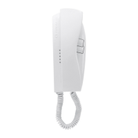
When using the interface FT11D with the telephone
ST740 it is necessary to programme the buttons dedi-
cated to the intercom functions (see page 162).
Note
For wires dimensioning refer to the installation recom-
mendations and table on page 26.
PA = Door release button (optional)
SE = Electric door lock (12Vac-1Amax.)
Note
For wires dimensioning refer to the installation
recommendations and table on page 26.
Trunk line
Trunk lines
 Loading...