81
(MT12 - Gb2004)
I
NTERCOMS *
V
IDEOINTERCOMS *
T
ELECOMMUNICATION
M
O
D
Y
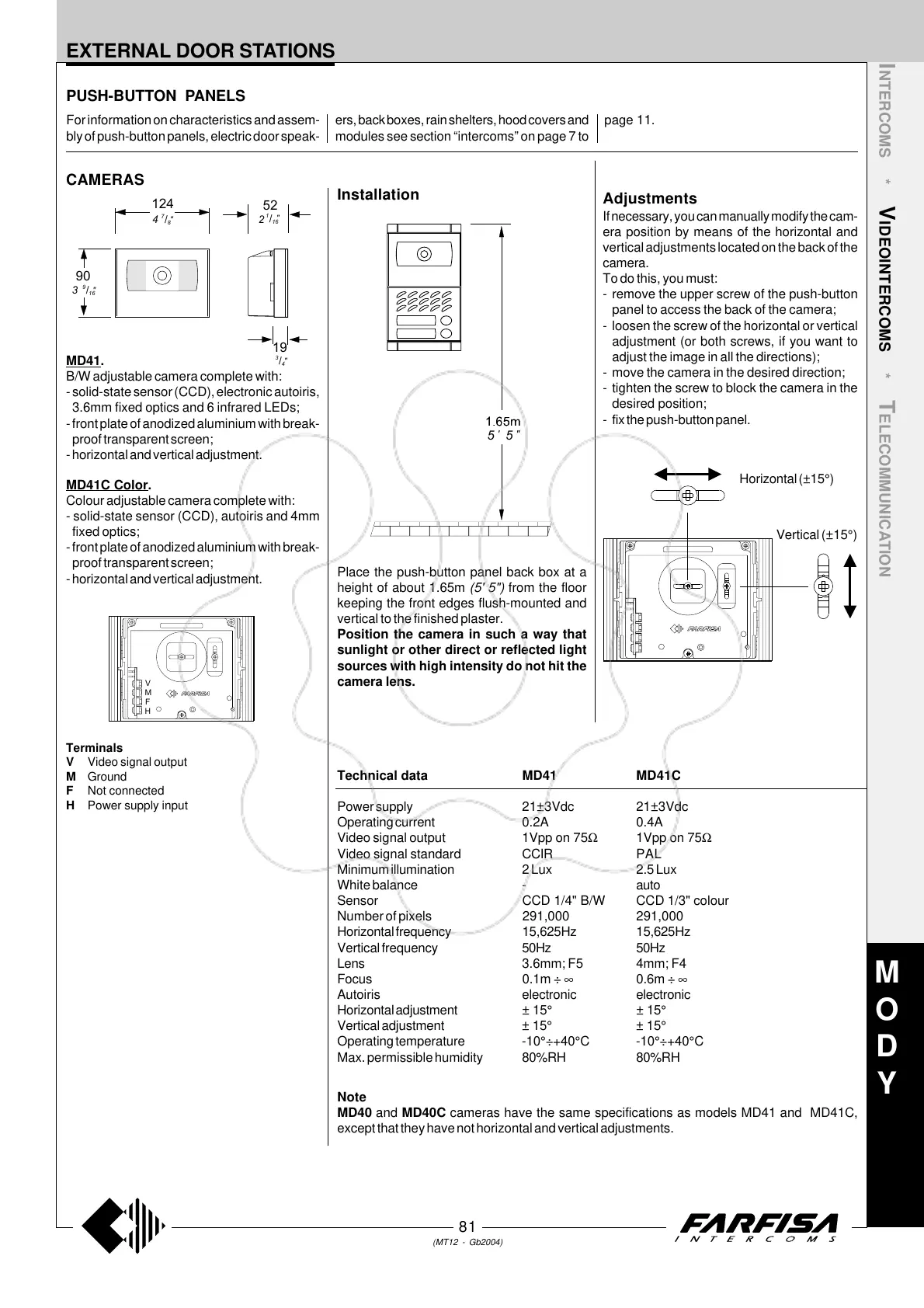
Place the push-button panel back box at a
height of about 1.65m (5' 5") from the floor
keeping the front edges flush-mounted and
vertical to the finished plaster.
Position the camera in such a way that
sunlight or other direct or reflected light
sources with high intensity do not hit the
camera lens.
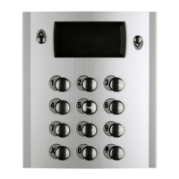
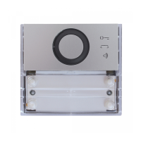
PUSH-BUTTON PANELS
MD41.
B/W adjustable camera complete with:
- solid-state sensor (CCD), electronic autoiris,
3.6mm fixed optics and 6 infrared LEDs;
- front plate of anodized aluminium with break-
proof transparent screen;
- horizontal and vertical adjustment.
MD41C Color.
Colour adjustable camera complete with:
- solid-state sensor (CCD), autoiris and 4mm
fixed optics;
- front plate of anodized aluminium with break-
proof transparent screen;
- horizontal and vertical adjustment.
Terminals
V Video signal output
M Ground
F Not connected
H Power supply input
H
F
M
V
EXTERNAL DOOR STATIONS
CAMERAS
Technical data MD41 MD41C
Power supply 21±3Vdc 21±3Vdc
Operating current 0.2A 0.4A
Video signal output 1Vpp on 75Ω 1Vpp on 75Ω
Video signal standard CCIR PAL
Minimum illumination 2 Lux 2.5 Lux
White balance - auto
Sensor CCD 1/4" B/W CCD 1/3" colour
Number of pixels 291,000 291,000
Horizontal frequency 15,625Hz 15,625Hz
Vertical frequency 50Hz 50Hz
Lens 3.6mm; F5 4mm; F4
Focus 0.1m ÷ ∞ 0.6m ÷ ∞
Autoiris electronic electronic
Horizontal adjustment ± 15° ± 15°
Vertical adjustment ± 15° ± 15°
Operating temperature -10°÷+40°C -10°÷+40°C
Max. permissible humidity 80%RH 80%RH
Installation
For information on characteristics and assem-
bly of push-button panels, electric door speak-
ers, back boxes, rain shelters, hood covers and
modules see section “intercoms” on page 7 to
page 11.
Adjustments
If necessary, you can manually modify the cam-
era position by means of the horizontal and
vertical adjustments located on the back of the
camera.
To do this, you must:
- remove the upper screw of the push-button
panel to access the back of the camera;
- loosen the screw of the horizontal or vertical
adjustment (or both screws, if you want to
adjust the image in all the directions);
- move the camera in the desired direction;
- tighten the screw to block the camera in the
desired position;
- fix the push-button panel.
Horizontal (±15°)
Vertical (±15°)
Note
MD40 and MD40C cameras have the same specifications as models MD41 and MD41C,
except that they have not horizontal and vertical adjustments.
5
'
5
"
"
16
/
1
4
"
8
/
7
52
124
90
2
"
16
/
9
"
4
/
3
19
3