30
(MT12 - Gb2004)
Si 11MO/1
I
NTERCOMS *
V
IDEOINTERCOMS *
T
ELECOMMUNICATION
INTERCOMS CONNECTED TO 1 EXTERNAL DOOR STATION.
Q.ty Article Description
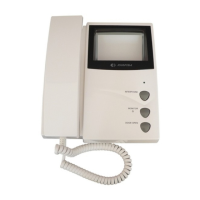
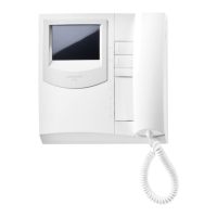
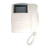
... PT 510 * Project series intercom with 1 call button
1 PRS220 Power supply
1 PA ** Door release push-button (optional)
1 SE ** Electric door lock (12VAC-1A)
Door station series Mody (for items selection refer to pages 12÷15)
1 row 2 row
... MD71÷74 MD71÷74 Module frames with back box
1 MD10-11-12 MD10-122-124 Modules for electric door speaker
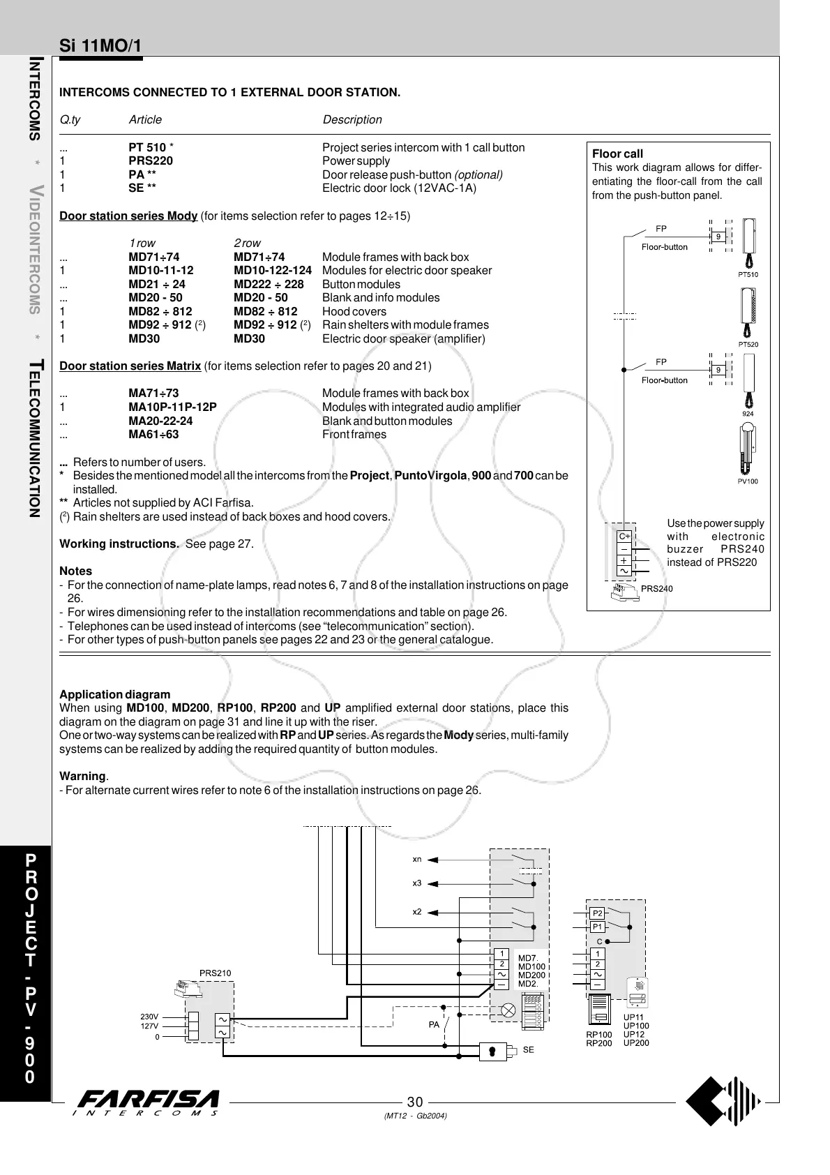
... MD21 ÷ 24 MD222 ÷ 228 Button modules
... MD20 - 50 MD20 - 50 Blank and info modules
1 MD82 ÷ 812 MD82 ÷ 812 Hood covers
1 MD92 ÷ 912 (
2
) MD92 ÷ 912 (
2
) Rain shelters with module frames
1 MD30 MD30 Electric door speaker (amplifier)
Door station series Matrix (for items selection refer to pages 20 and 21)
... MA71÷73 Module frames with back box
1 MA10P-11P-12P Modules with integrated audio amplifier
... MA20-22-24 Blank and button modules
... MA61÷63 Front frames
... Refers to number of users.
* Besides the mentioned model all the intercoms from the Project, PuntoVirgola, 900 and 700 can be
installed.
** Articles not supplied by ACI Farfisa.
(
2
) Rain shelters are used instead of back boxes and hood covers.
Working instructions. See page 27.
Notes
- For the connection of name-plate lamps, read notes 6, 7 and 8 of the installation instructions on page
26.
- For wires dimensioning refer to the installation recommendations and table on page 26.
- Telephones can be used instead of intercoms (see “telecommunication” section).
- For other types of push-button panels see pages 22 and 23 or the general catalogue.
Application diagram
When using MD100, MD200, RP100, RP200 and UP amplified external door stations, place this
diagram on the diagram on page 31 and line it up with the riser.
One or two-way systems can be realized with RP and UP series. As regards the Mody series, multi-family
systems can be realized by adding the required quantity of button modules.
Warning.
- For alternate current wires refer to note 6 of the installation instructions on page 26.
P
R
O
J
E
C
T
-
P
V
-
9
0
0
Floor call
This work diagram allows for differ-
entiating the floor-call from the call
from the push-button panel.
Use the power supply
with electronic
buzzer PRS240
instead of PRS220