63
(MT12 - Gb2004)
CT1 CT2
CT3 CT4
CT5
CT6
2
3
4
5
1
2
9
3
5
7
P1
6
P2
P3
P4
P5
1
2
9
3
5
7
P1
P2
P3
6
P4
P5
1
2
9
3
5
7
P1
P2
6
P3
P4
P5
1
2
9
3
5
7
P1
P2
P3
P4
6
P5
7
P1
P2
P3
P4
P5
6
1
2
9
3
5
x2
x3
x4
x5
xn
1
2
9
3
5
7
6
P1
P2
P3
P4
P5
PT520+
PT501
PT520+
PT501
PT520+
PT501
PT520+
PT501
PT520+
PT501
PT520+
PT501
1
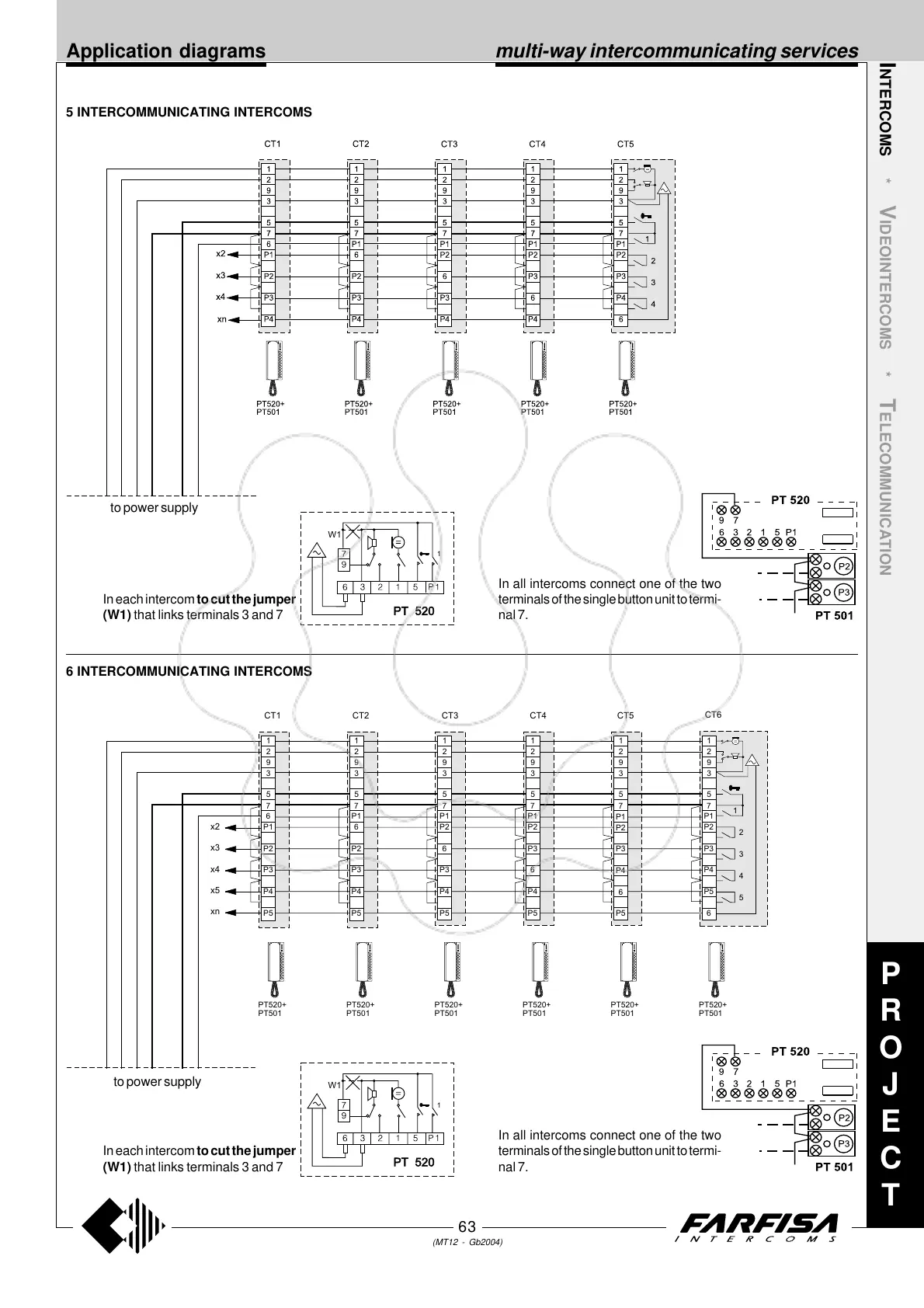
5 INTERCOMMUNICATING INTERCOMS
I
NTERCOMS *
V
IDEOINTERCOMS *
T
ELECOMMUNICATION
6 INTERCOMMUNICATING INTERCOMS
Application diagrams
to power supply
to power supply
P
R
O
J
E
C
T
In each intercom to cut the jumper
(W1) that links terminals 3 and 7
W1
1
PT 520
In all intercoms connect one of the two
terminals of the single button unit to termi-
nal 7.
In each intercom to cut the jumper
(W1) that links terminals 3 and 7
W1
1
PT 520
In all intercoms connect one of the two
terminals of the single button unit to termi-
nal 7.
multi-way intercommunicating services