64
(MT12 - Gb2004)
Application diagrams
I
NTERCOMS *
V
IDEOINTERCOMS *
T
ELECOMMUNICATION
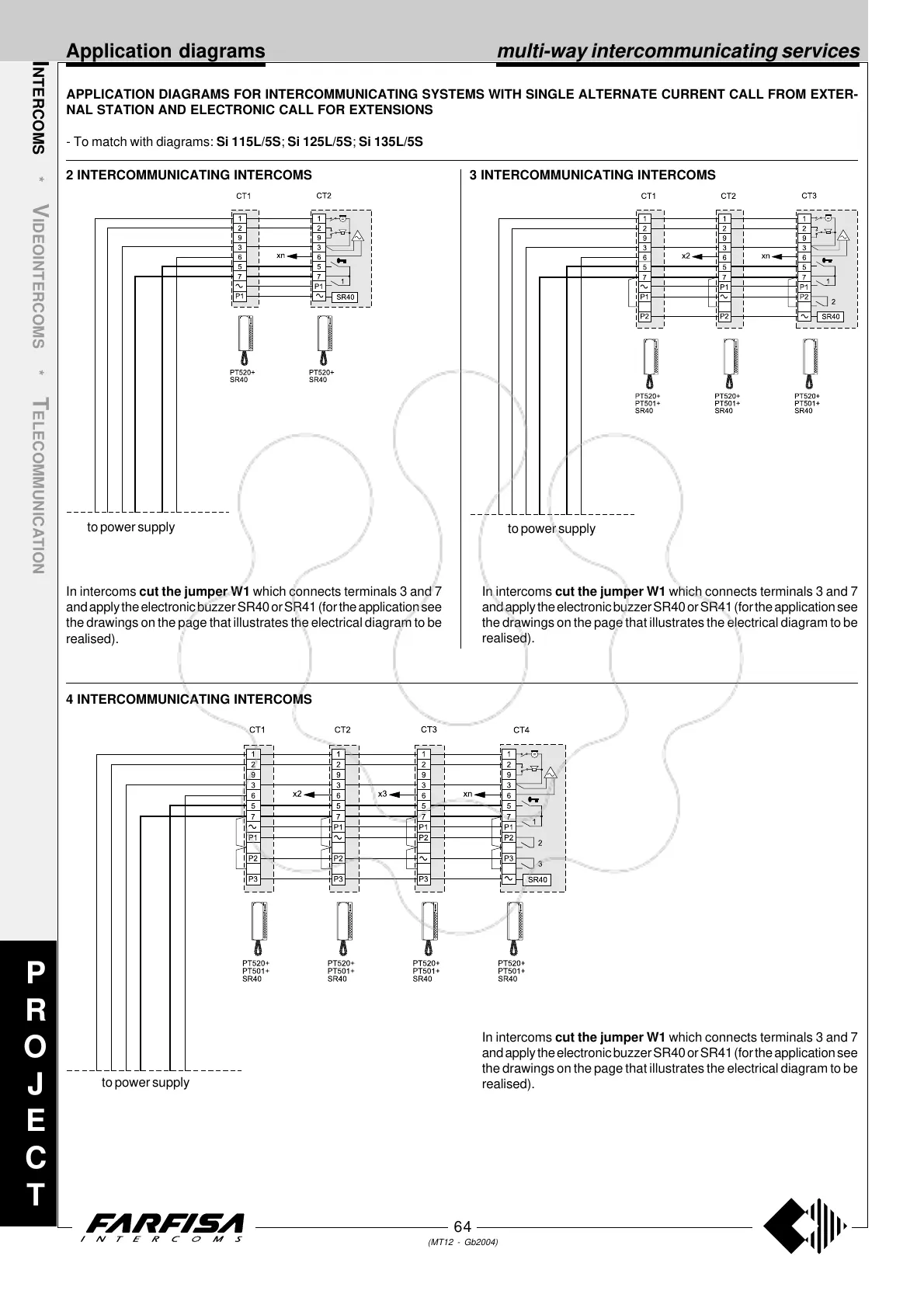
APPLICATION DIAGRAMS FOR INTERCOMMUNICATING SYSTEMS WITH SINGLE ALTERNATE CURRENT CALL FROM EXTER-
NAL STATION AND ELECTRONIC CALL FOR EXTENSIONS
- To match with diagrams: Si 115L/5S; Si 125L/5S; Si 135L/5S
multi-way intercommunicating services
3 INTERCOMMUNICATING INTERCOMS
4 INTERCOMMUNICATING INTERCOMS
2 INTERCOMMUNICATING INTERCOMS
to power supply
to power supply
to power supply
In intercoms cut the jumper W1 which connects terminals 3 and 7
and apply the electronic buzzer SR40 or SR41 (for the application see
the drawings on the page that illustrates the electrical diagram to be
realised).
In intercoms cut the jumper W1 which connects terminals 3 and 7
and apply the electronic buzzer SR40 or SR41 (for the application see
the drawings on the page that illustrates the electrical diagram to be
realised).
In intercoms cut the jumper W1 which connects terminals 3 and 7
and apply the electronic buzzer SR40 or SR41 (for the application see
the drawings on the page that illustrates the electrical diagram to be
realised).
P
R
O
J
E
C
T
 Loading...