5
(MT12 - Gb2004)
I
NTERCOMS *
V
IDEOINTERCOMS *
T
ELECOMMUNICATION
INTERNAL STATIONS
INTERCOMS PROJECT series
2136
2916357
C
B
9
X2
7
X1
9
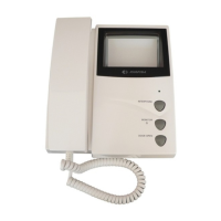
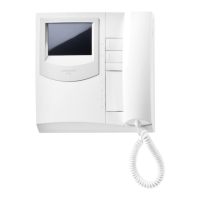
PT510. Two-colour intercom for 4+1 systems
connected to one or more door stations. Com-
plete with push-button, spiral cord, buzzer, elec-
tronic microphone. Wall-mounted with screws
or fixed to back box.
PT510N. Colour: beige.
PT510W. Colour: white.
PT524W. White colour finish with carbon mi-
crophone.
Terminals
1 microphone
2 loudspeaker
3 ground
5 door release push-button (max 1A)
6 buzzer (0.2A)
9 electronic bell input
Two of the following
modules can be si-
multaneously applied
inside the intercoms:
- RL36 relay module;
- SM50 private con-
versation module;
- SR40 electronic bell
module;
- SR41 electronic
buzzer module.
6
W1
2
91
3
57
+
-
9
7
SR40. Electronic bell module (see inter-
communication diagrams).
Terminals
power supply call in-
put (12Vac-0.5A)
X1 power supply input
(12Vac-0.3A)
X2 call input (ground con-
trol)
SR41. Electronic buzzer module. It can be
used to differentiate calls from external door
stations or external door station and
intercommunicating stations (in this
case it can replace electronic bell
module SR40).
Terminals
4 power supply input (13Vac-70mA;
9÷20Vdc-15mA)
3 ground
SM50. Private conversation module (see
pages 32 and 100).
Terminals
C audio line receiver
B audio line transmitter
- ground
PT538. Table adapter for Project series in-
tercoms, with weighted base, junction box and
2.4m connection cable with 13 wires.
RL36
or
SM50
or
SR40
or
SR41
PT501
PT502
PT515
2136
C
B
SM 50
R1
10K
9 7
2315P16
X2
7
X1
9
PT501
43
P
R
O
J
E
C
T