76
(MT12 - Gb2004)
I
NTERCOMS *
V
IDEOINTERCOMS *
T
ELECOMMUNICATION
INTERNAL STATIONS
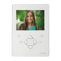
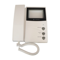
PT5860. Two-colour reflex videointercom with
audio-video privacy, electronic microphone,
differentiated double electronic ringing sounds
(modulated and continuous note) and terminal
board for the connection to the wall-bracket.
With two buttons, one for control switch ON and
one for door lock release, and 6 supplementary
buttons, that can be added for additional serv-
ices such as: control switch ON, intercommuni-
cating calls, stair lights, door lock release, etc.
The buttons are included in the kit of the
videointercom. The maximum acceptable cur-
rent to the button terminals is 60mA. For higher
currents use relay unit art.1471.
It can be installed on the wall by using the wall-
bracket art.WB5600 or WB5660. For particu-
lar needs it is possible to separate the common
of the buttons labeled P4, P5 and P6 by cutting
the W1 jumper on the wall-bracket. The buttons
have the 2C terminal in common. In this case
the maximum acceptable current to the three
buttons is 0.5A.
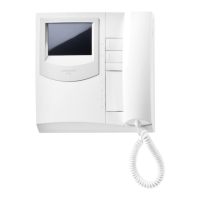
PT5860W. This model has the same features
as the previous one, but with a white finish.
Technical data
Power Supply 18÷24Vdc
Operating current 0.6A
Video tube 4.5" - 90°
Television standard 625 lines
Horizontal frequency 15625Hz
Vertical frequency 50Hz
Bandwidth >5MHz
Video signal on 75Ω 0.8÷1.5Vpp
Starting up time 5÷7 sec.
Operating temperature 0°÷+50°C
Max. permissible humidity 90%RH
Videointercoms Project series
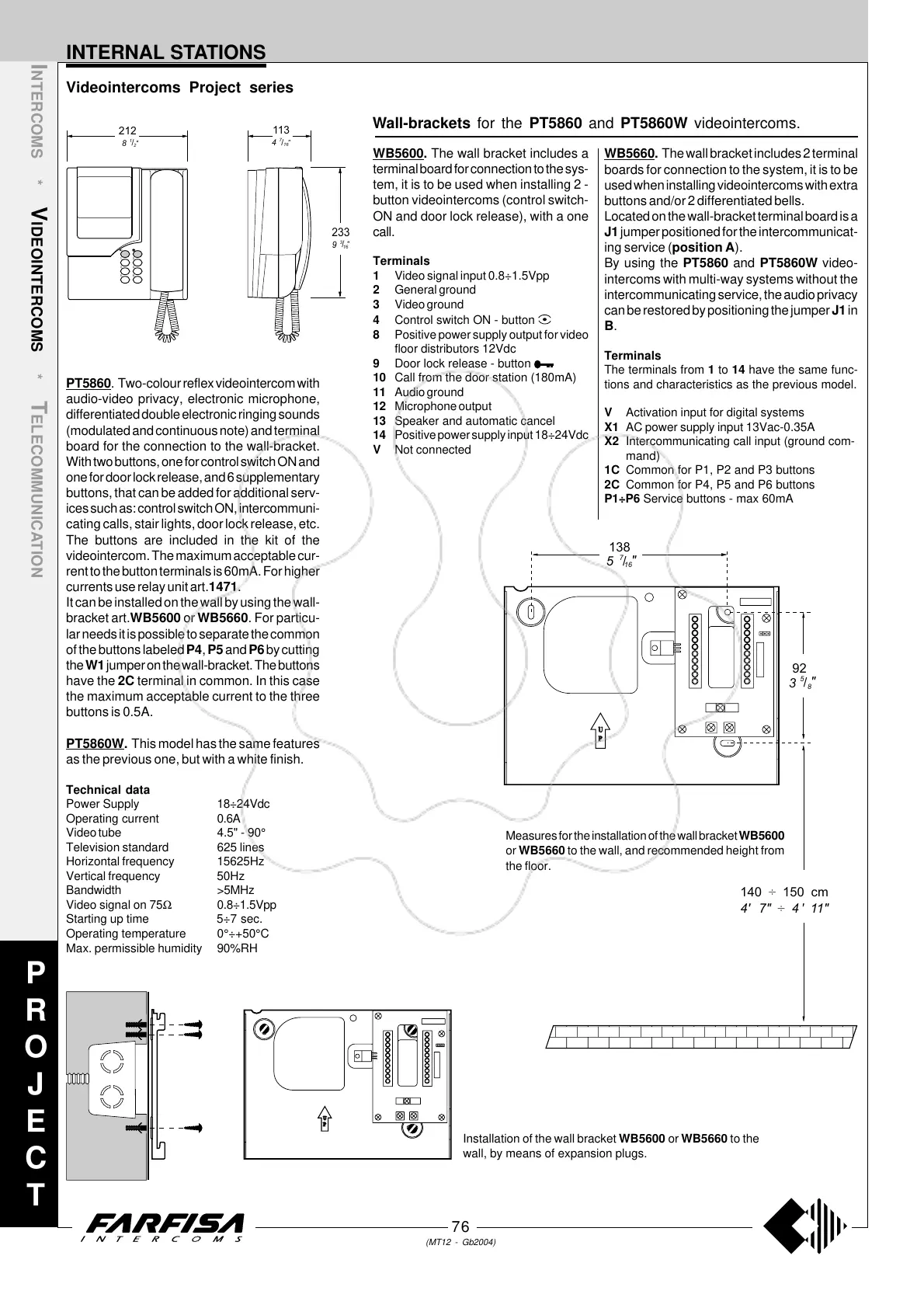
Measures for the installation of the wall bracket WB5600
or WB5660 to the wall, and recommended height from
the floor.
U
P
Installation of the wall bracket WB5600 or WB5660 to the
wall, by means of expansion plugs.
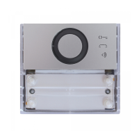
Wall-brackets for the PT5860 and PT5860W videointercoms.
WB5660. The wall bracket includes 2 terminal
boards for connection to the system, it is to be
used when installing videointercoms with extra
buttons and/or 2 differentiated bells.
Located on the wall-bracket terminal board is a
J1 jumper positioned for the intercommunicat-
ing service (position A).
By using the PT5860 and PT5860W video-
intercoms with multi-way systems without the
intercommunicating service, the audio privacy
can be restored by positioning the jumper J1 in
B.
Terminals
The terminals from 1 to 14 have the same func-
tions and characteristics as the previous model.
V Activation input for digital systems
X1 AC power supply input 13Vac-0.35A
X2 Intercommunicating call input (ground com-
mand)
1C Common for P1, P2 and P3 buttons
2C Common for P4, P5 and P6 buttons
P1÷P6 Service buttons - max 60mA
WB5600. The wall bracket includes a
terminal board for connection to the sys-
tem, it is to be used when installing 2 -
button videointercoms (control switch-
ON and door lock release), with a one
call.
Terminals
1 Video signal input 0.8÷1.5Vpp
2 General ground
3 Video ground
4 Control switch ON - button
8 Positive power supply output for video
floor distributors 12Vdc
9 Door lock release - button
10 Call from the door station (180mA)
11 Audio ground
12 Microphone output
13 Speaker and automatic cancel
14 Positive power supply input 18÷24Vdc
V Not connected
P
R
O
J
E
C
T
233
9
"
16
/
3
212
8
"
2
/
1
113
4
"
16
/
7
6
5
2
1
4
3
U
P
aaaaaaaaaaaaaaa
aaaaaaaaaaaaaaa
138
140 150 cm÷
3
5
"
"
8
16
/
/
92
5
7
4" 7" 4" 11"÷