92
(MT12 - Gb2004)
I
NTERCOMS *
V
IDEOINTERCOMS *
T
ELECOMMUNICATION
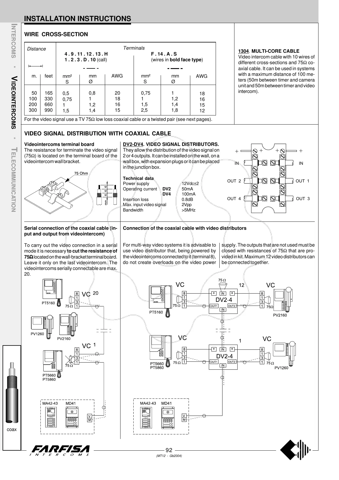
1304. MULTI-CORE CABLE
Video intercom cable with 10 wires of
different cross-sections and 75Ω co-
axial cable. It can be used in systems
with a maximum distance of 100 me-
ters (50m between timer and camera
unit and 50m between timer and video
intercom).
VIDEO SIGNAL DISTRIBUTION WITH COAXIAL CABLE
Serial connection of the coaxial cable (in-
put and output from videointercom)
To carry out the video connection in a serial
mode it is necessary to cut the resistance of
75
ΩΩ
ΩΩ
Ω located on the wall-bracket terminal board.
Leave it only on the last videointercom. The
videointercoms serially connectable are max.
20.
Connection of the coaxial cable with video distributors
For multi-way video systems it is advisable to
use video distributor that, being powered by
the videointercoms connected to it (terminal 8),
do not create overloads on the video power
supply. The outputs that are not used must be
closed with resistances of 75Ω that are pro-
vided in kit. Maximum 12 video distributors can
be connected together.
DV2-DV4. VIDEO SIGNAL DISTRIBUTORS.
They allow the distribution of the video signal on
2 or 4 outputs. It can be installed on the wall, on a
wall box, with expansion plugs or it can be placed
in the junction box.
Technical data
Power supply 12Vdc±2
Operating current DV2 50mA
DV4 100mA
Insertion loss 0.8dB
Max. input video signal 2Vpp
Bandwidth >5MHz
+
+
IN
IN
OUT 1
OUT 3
OUT 4
+
+
OUT 2
Videointercoms terminal board
The resistance for terminate the video signal
(75Ω) is located on the terminal board of the
videointercom wall bracket.
INSTALLATION INSTRUCTIONS
coax
WIRE CROSS-SECTION
For the video signal use a TV 75Ω low loss coaxial cable or a twisted pair (see next pages).
m.
50
100
200
300
mm²
S
0,5
0,75
1
1,5
mm
Ø
0,8
1
1,2
1,4
Terminals
Distance
mm²
S
0,75
1
1,5
2,5
mm
Ø
1
1,2
1,4
1,8
4 . 9 . 11 . 12 . 13 . H
1 . 2 . 3 . D . 10 (call)
F . 14 . A . S
(wires in bold face type)
AWG
20
18
16
15
AWG
18
16
15
12
feet
165
330
660
990
 Loading...