Farmer 400
Fav 700
Fav 900
Electronics / Sensors
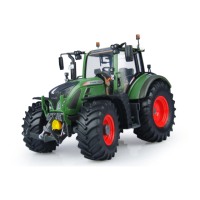
Electrical circuit diagram - speed sensor
A
General
23.2.2001
9700 000010
A
a
1/1
Capitel Docu-No.
Index
Date Version
Page
Electrical circuit diagram - speed sensor
PM-Picturemodule
PM-Picturemodule
Text-module
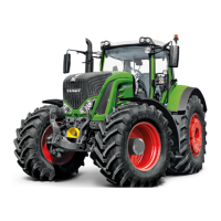
Speed sensor pin assignment
1 = Earth
2 = Speed signal
3 = + supply 12 to 14 VDC
Text-module
Measure resistance at pin 2 and pin 1
Hall-effect sensor disconnected (no + supply)
Resistance R =
18 kohms
Text-module
Measure signal voltage at pin 2 and pin 1
ECU A002 supplies basic signal voltage of approx. 7.3 VDC to pin 2.
Ratchet wheel setting A
Signal voltage = approx. 5.4 VDC , resistance 18 kohms
Ratchet wheel setting B
Signal voltage = approx. 1.1 VDC , total resistance (parallel connection) from 18 kohms and 1 kohm
Text-module
Measure + supply at pin 3 and pin 1
Voltage = 12 to 14 VDC (depending on on-board power supply)
PMTAB_Picture
PMTAB_Picture
 Loading...