15
© Ferno s.r.l. Rel.05042024
XT Series Extrication Devices
BLACK GROIN RESTRAINT
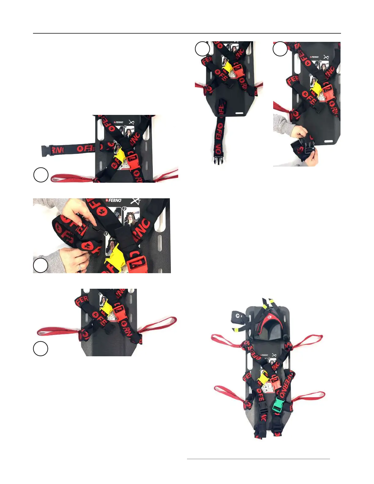
1. Insert the slot of the restraint with the female end into hole
no. 12 on the extrication device, with the stitching facing the
operator (Figure 8A).
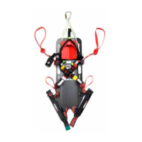
2. Insert the black buckle into the newly positioned restraint
slot (Figure 8B).
3. Pull the restraint to tighten the loop knot (Figure 5C).
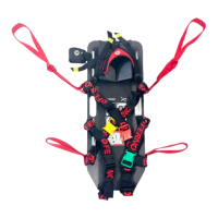
4. Insert the slot of the restraint with the male end into hole
no. 9, with the stitching facing the operator (Figure 9A).
5. Insert the black buckle into the newly positioned restraint
slot (Figure 9B).
6. Pull the restraint to tighten the loop knot.
8A
8B
8C
Figure 8 - Black restraint application
(end with female buckle)
9A 9B
Figure 9 - Black restraint application
(end with male buckle)
GREEN GROIN RESTRAINT
1. Insert the slot of the restraint with the male end into hole
no. 5 on the extrication device, with the stitching facing the
operator.
2. Insert the green buckle into the newly positioned restraint
slot.
3. Pull the restraint to tighten the loop knot.
4. Insert the slot of the restraint with the male end into hole
no. 8, with the stitching facing the operator.
5. Insert the green buckle into the newly positioned restraint
slot.
6. Pull the restraint to tighten the loop knot.
Figure 10 - Correct positioning of restraints