5.2 ON-THE-SPOT DIAGNOSIS
LED displays
Bus node
The LEDs on the cover of the bus node indicate
the operating status of the valve terminal.
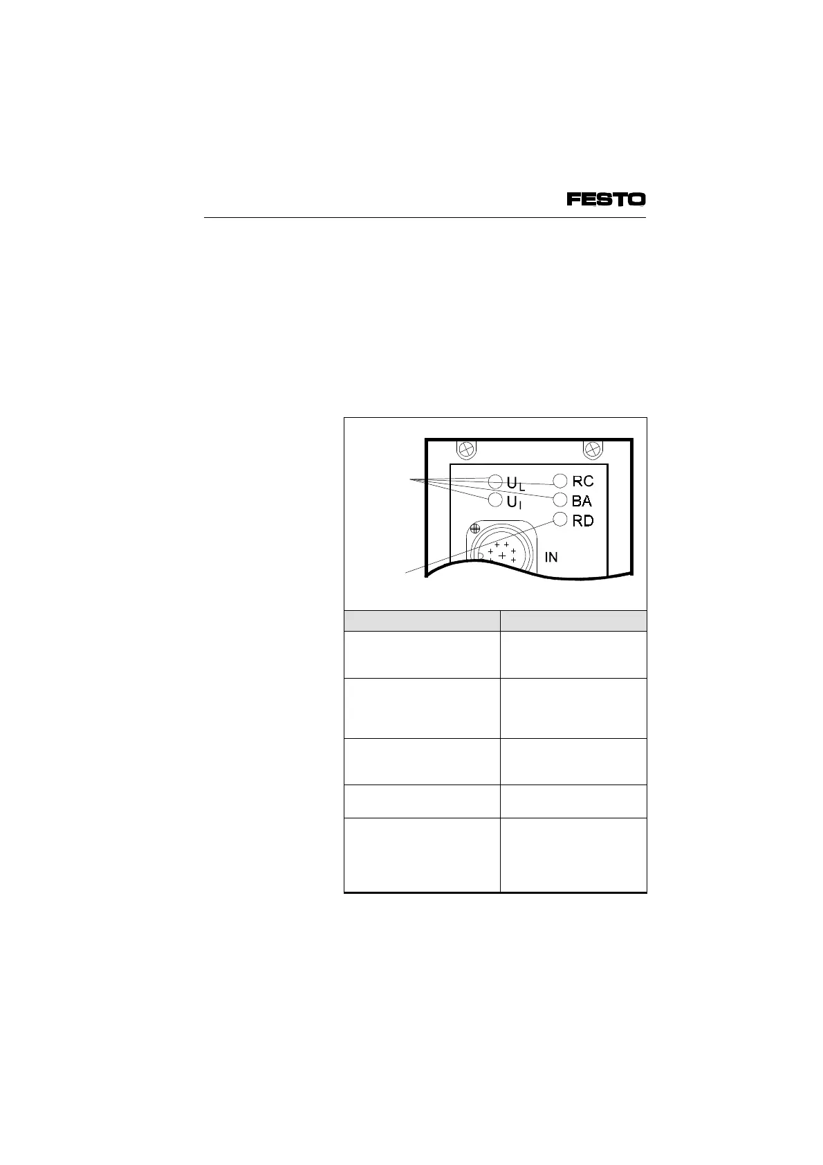
Fig. 5/2: LEDs on the bus node
LED designation Meaning
V
L
Operating voltage
display of internal
electronic components
Lights up when
operating voltage is
applied at pin 1
V
I
Operating voltage
display of
INTERBUS
interface
Lights up when
electronic components of
INTERBUS interface are
ready to operate
RC Remote bus check Lights up when there is
a connection to the
master
BA Bus active Lights up during data
transmission
RD Remote bus disable Lights up if data
transmission to bus is
interrupted or if interface
"REMOTE OUT" is
switched off
Red LED
(error display)
Green LED
(operating
status)
VIFB6 - 03/05 5. Diagnosis/Error Treatment
5-4
9809c