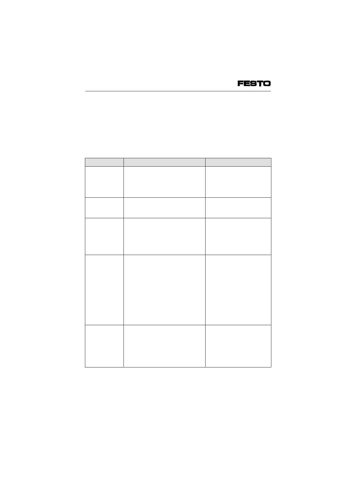
Possible LED displays on the operating status of
the valve terminal are shown below.
1. Error displays RC, BA, RD;
(• = LED lights up,
*
= LED blinks,
o = LED out)
LEDs Operating status Error treatment
• VL o RC
• VI o RC
o RD
Valve test mode is switched on
If valves do not switch, hardware
error
Exit self-test mode by
switching off operating
voltage
Service case
• V
L
• RC
• V
I
o BA
o RD
No data transmission Check operating status of
controller board
• V
L
o RC
• V
I
o BA
• RD
INTERBUS fault; either:
• bus not connected or interrupted
• interface switched off
• Check or connect bus
cable
• Programmed switch off
by master
• Reset status
• V
L
o RC
• V
I
o BA
*
RD*)
*) RD
short on
long off
Module not fitted correctly:
• more than 12 I/O modules fitted
• module type not permitted
or:
• logical address range exceeded
(more than 60 inputs or more
than 64 outputs)
or:
• no I/O or P module fitted
• Reduce number of I/O
modules
• Use only permitted
modules
• Reduce I/O or P modules
• Fit at least one permitted
module
• V
L
o RC
•
V
I
o BA
*
RD*)
*) RD
short off
long on
Hardware error in a module Service case
Fig. 5/3a: Part 1 – LED error messages
VIFB6 - 03/05 5. Diagnosis/Error Treatment
9809c 5-5
 Loading...


