Calculating with a formula
Proceed as follows:
1. Calculate the maximum current consumption
of the inputs and electronic components (I
1
)
as well as of the outputs/valves (I
2
).
2. Calculate the lowest voltage (V
Omin
) to be ex-
pected on the power unit during operation.
Take into account here:
• the load dependency on the power unit
• the fluctuations in the primary power
voltage.
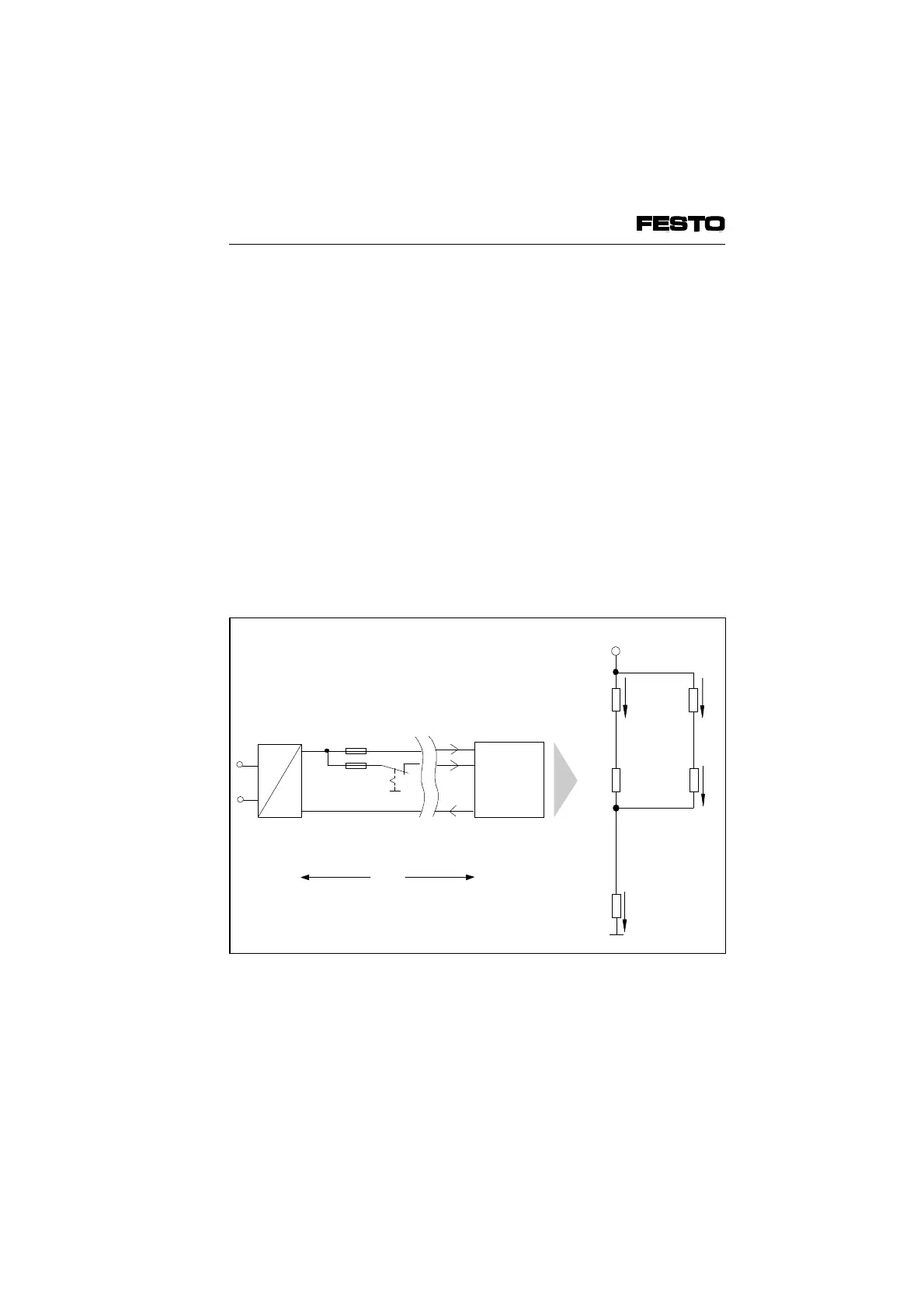
3. Enter the values in the appropriate formula.
The equivalent circuit diagram and the
example explain the correlation.
AC
DC
0 V
V
O
*)
3.15 AT
10 AT
I
1
I
2
Pin 1
Pin 2
Pin 3
Valve terminal
R
L0
0 V
V
L2
+ V
L1
V
term.
Cable
resistor (returning)
R
I2
R
I1
V
O
R
L1
Cable resistor
(incoming)
V
L2
R
L2
Distance (cable length)
L
Operating voltage supply
Equivalent circuit diagram
I
0
*) Operating voltage can be switched off separately
Fig. A/3: Cable length (L) and cable resistor (R
L)
VIFB6- 03/05 Appendix A
9809c A-9