The following connection, display and operating
elements are to be found on the pneumatic ISO
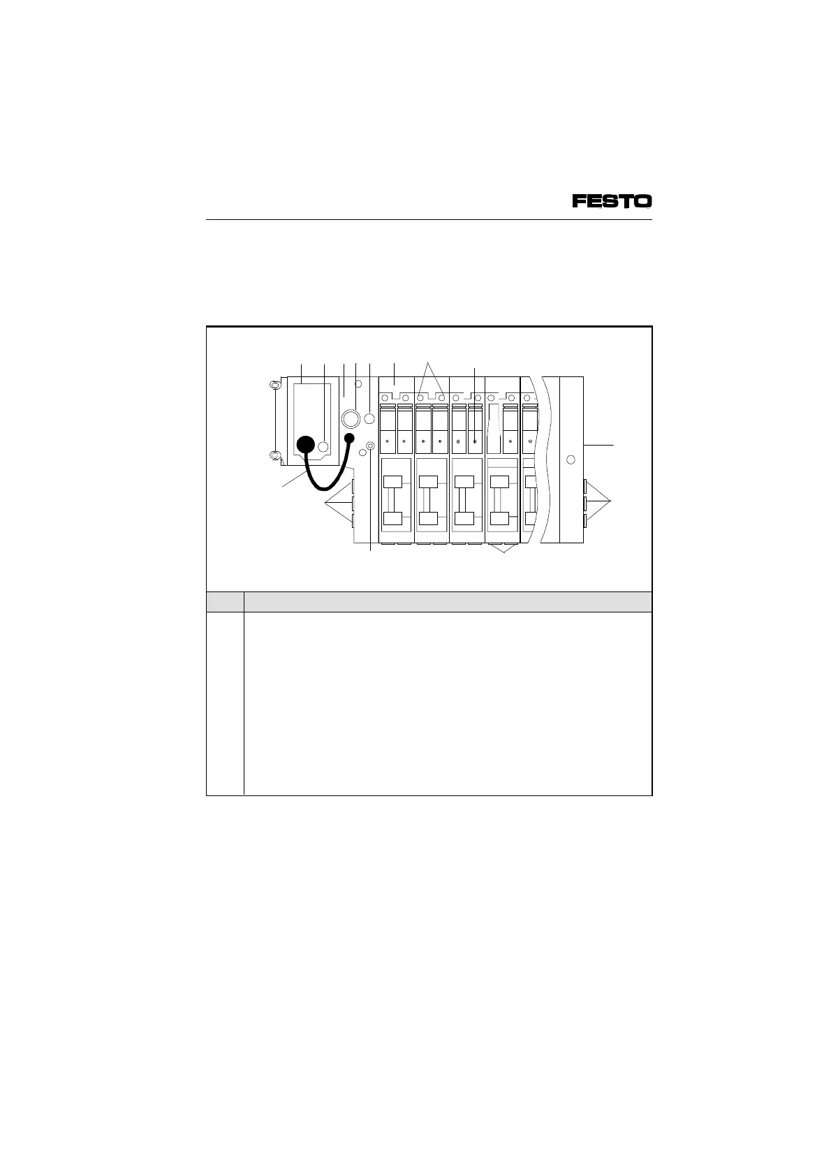
modules type 05:
The electronic modules are described in the
section "Description of components type 03".
No. Meaning
1
2
3
4
5
6
7
8
9
10
11
12
Node with LEDs and INTERBUS connection, detailed description see
chapter "Installation"
Fuse for inputs/sensors (pin 1)
Adapter plate
Operating voltage connection of valve terminal type 05
Fuse for valves (pin 2)
Valve location inscription field
Yellow LEDs (per pilot solenoid)
Manual override (per pilot solenoid, pressing or locking)
External air control connection
Common connections
Work connections (per valve)
Adapter cable for operating voltage of node and I/O modules
Fig. 1/6: Operating, display and connection elements of ISO modules
type 05
10
12
9
9
10
6 7
452
3
1
VIFB6 - 03/05 1. System summary
1-8
9809c