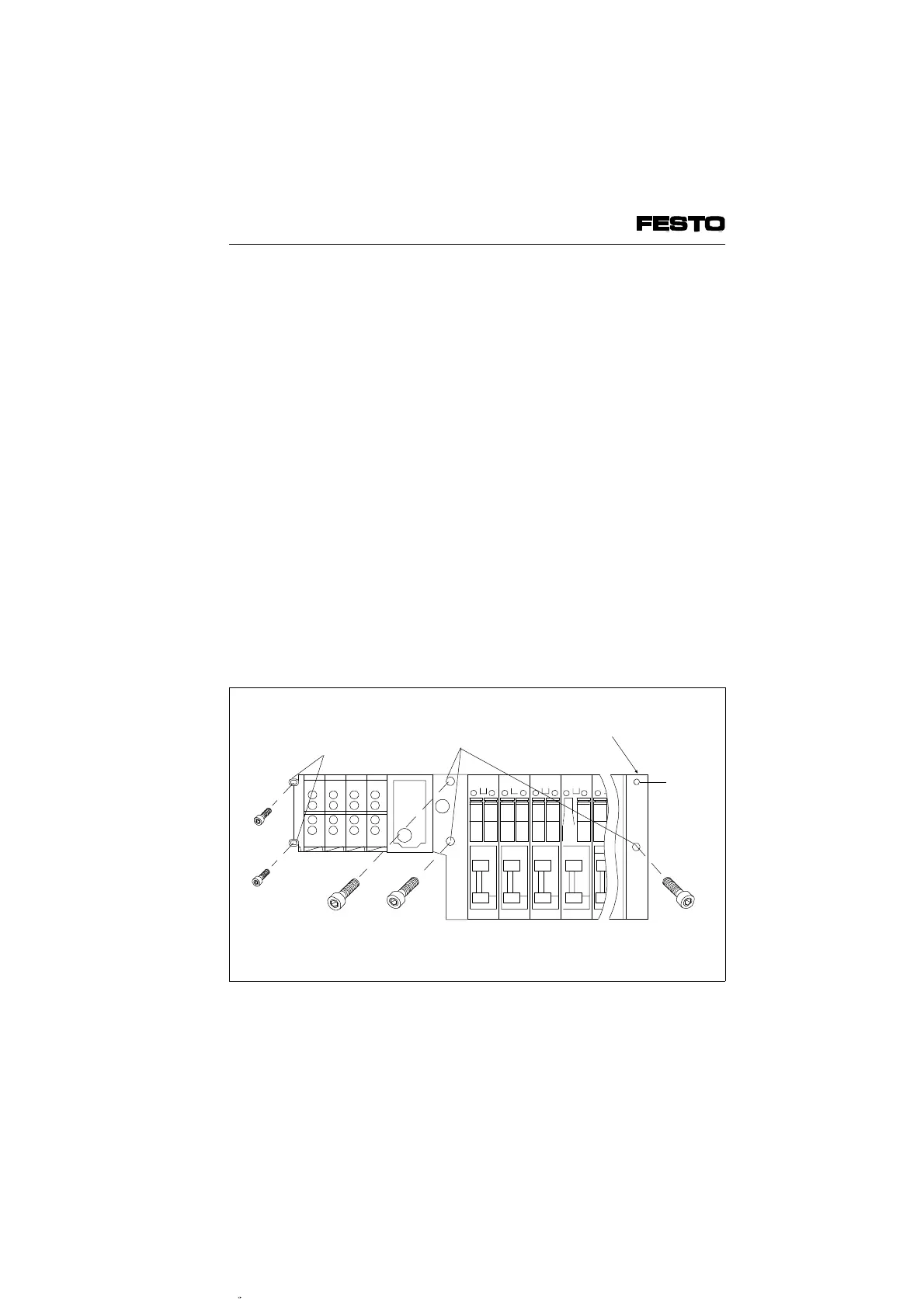
Fasten the terminal as follows:
• with three M10 screws on the adapter plate
and on the right-hand end plate (2)
• with two M6 screws on the left-hand end
plate (1)
If required, use the following additional fastening
methods:
• the hole on the bottom of the right-hand end
plate with an M10 thread
("blind hole" (3))
• the supporting angles for the I/O modules
(see fitting instructions supplied with the
angles)
The terminal can be fitted in any desired
position. If necessary, use spacers as well as
the mounting and transport threads M8 (e.g.
lifting eye bolts for crane hooks).
M10
3
Thread M8 for lifting eye bolts
2
1
M6
Fig. 2/6: Fitting the ISO valve terminal type 05 on the wall
VIFB6 - 03/05 2. Fitting
9809c 2-13