2. Open the strain relief on the rear part of the
housing. Pass the cable through as shown
below (see diagramm).
Cable outer diameter:
PG 7: 4.0 ... 6.0 mm
PG 9: 6.0 ... 8.0 mm
PG 13.5: 10.0 ...12.0 mm
Plugs/sockets (straight/angled):
•
Power supply socket: PG 7, 9 or 13.5
•
Sensor plug: PG 7
•
Bus cable socket: PG 7, 9 or 13.5
3. Remove 5 mm of insulation from the end of
the cable.
4. Fit the strands with cable end sleeves.
5. Connnect the ends of the cables.
6. Place the connection part onto the housing of
the plug/socket again and fasten both parts
with screws. Pull the cable back so that it is
not looped inside the housing.
7. Tighten the strain relief.
AAA
AAA
AAA
AAA
AA
AA
AAAA
AAAA
AA
AA
AAAA
AA
AAA
AAA
AAA
AAA
AAA
AAA
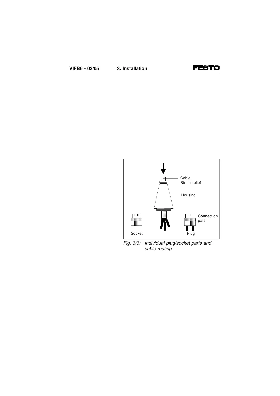
Cable
Housing
Strain relief
Socket
Fig. 3/3: Individual plug/socket parts and
cable routing
VIFB6 - 03/05 3. Installation
9809c 3-11