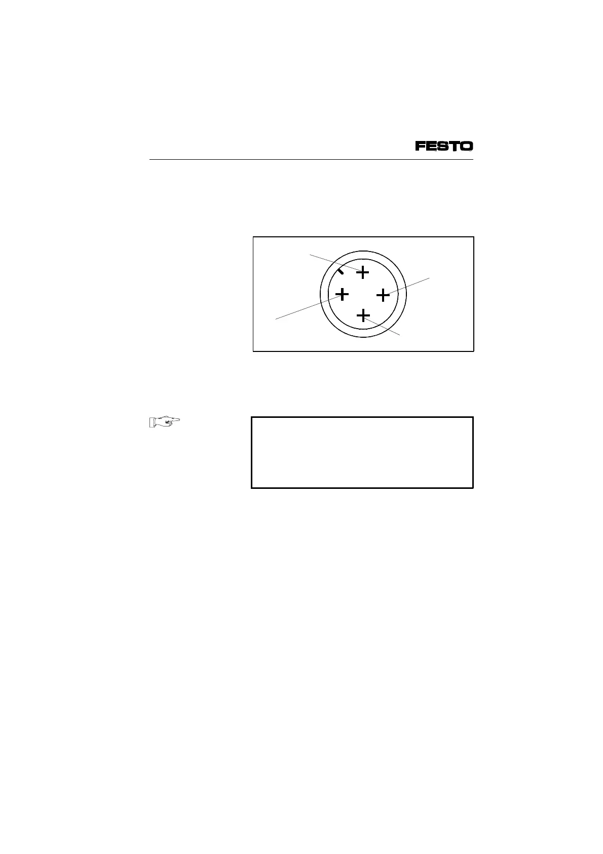
The diagram below shows the pin assignment of
the operating voltage connection on the adapter
plate.
Power unit
PLEASE NOTE
With common voltage supply for pin 1 (elec-
tronic components and inputs) and pin 2 (out-
puts/valves) the lower tolerance of
±
10 % for
both circuits must be observed.
Check the 24 V operating voltage of the outputs
whilst your system is operating. Make sure that
the operating voltage of the outputs lies within
the permitted tolerances even during full oper-
ation.
Recommendation
Use a closed loop power unit.
1
24 V supply
for electronic
components
and inputs
24 V supply
valves, outputs
Earth
connection
Fig. 3/14: Pin assignment of the operating
voltage connection (type 05)
VIFB6 - 03/05 3. Installation
9809c 3-33