When the power supply is switched on, the valve
terminal recognizes all available pneumatic mo-
dules (type 03: max. 13, type 05: 4, 8 or 12
valve locations) and digital input/output modules
automatically and assigns the appropriate ad-
dresses. If a valve location is not used (blanking
plate) or if a digital input/output is not connected,
the appropriate address is nevertheless as-
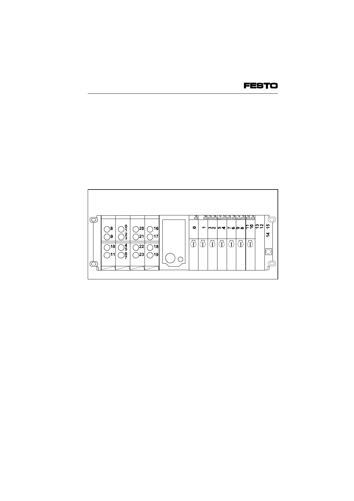
signed. The diagram below shows the addr.
assignment with mixed fitting.
Remarks on Fig. 4/4
• If single solenoid valves are fitted onto double
sub-bases, four addresses will be assigned
for valve solenoid coils.The higher address
remains unused (see address 3).
• If unused locations are sealed with blanking
plates, the addresses will still be assigned
(see addresses 12, 13).
• Due to the 4-bit orientated addressing of the
valve terminal, the address of the last loca-
tion is always rounded up to the full 4 bits
(unless all 4 bits are already used). Two ad-
dresses cannot therefore be used (see ad-
dresses 14, 15).
I module
4 inputs
I module
8 inputs
O module
4 outputs
O module
4 outputs
SINGLE
sub-base
DOUBLE
sub-base
Round
up
Fig. 4/4: Addr. assignment of a valve terminal with digital I/Os (type 03)
VIFB6 - 03/05 4. Commissioning
4-12
9809c