Festo Controller CECC
70
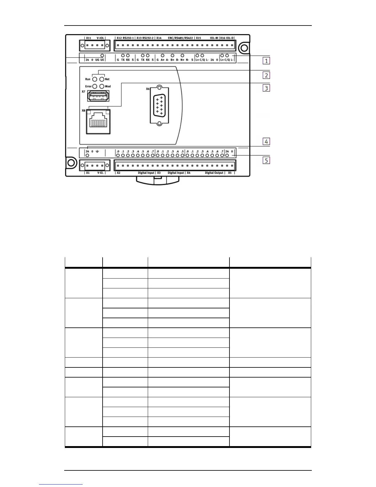
1
RS232, multiple interface ENC/RS422/RS485 and IO-Link
2
Operation (Run, Net, Error, Mod)
3
Ethernet
4
Power supply to the device (24 V)
5
I/O (inputs and outputs) and power supply for I/O
Figure: Status LEDs on the CECC-S
LED Sequence Meaning Comment
24 Volt Lights up green Device ready for operation Power supply
Does not light up Device switched off
Flashes green Undervoltage of the device
Run Lights up green Program running Application status
Lights up yellow Program is stopped
Does not light up Runtime system not started
Error Lights up red Class 4 error PLC runtime error
Flashes red Class 2 error
Does not light up No error/class 1 error
Net Flashes red Device identified Identification by FFT
Mod – – Reserved
Ethernet left Lights up green Data transfer with 100 Mbit Speed LED = Speed of data
transfer
Does not light up Data transfer with 10 Mbit
Ethernet right Lights up green Connection established Link/activity LED = connection
and data transfer
Flashes green Data transfer active
Does not light up No connection
I/Os Lights up green 24 V input Inputs and outputs
Lights up yellow 24 V output