Festo Controller CECC
71
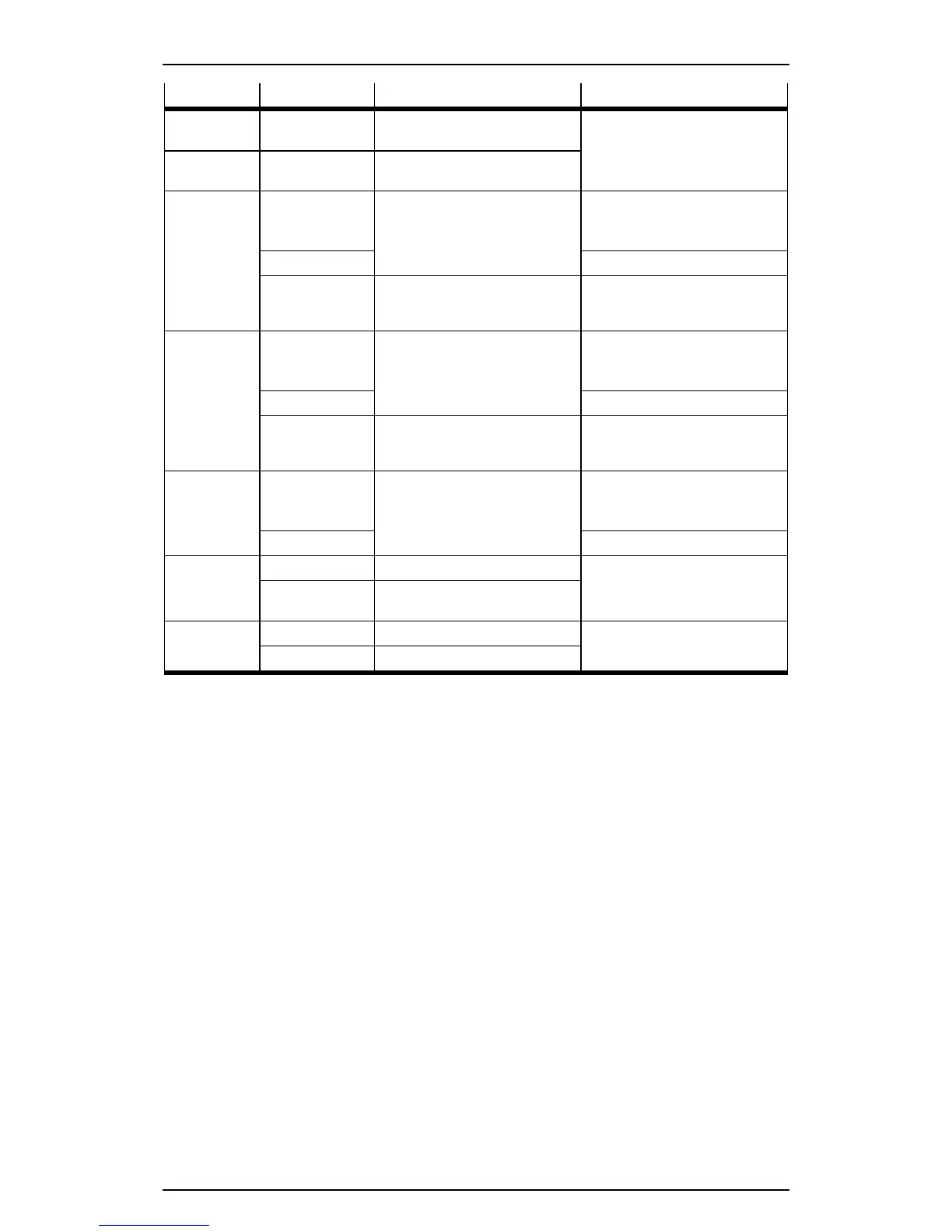
LED Sequence Meaning Comment
RS232-1/-2
TX
Lights up green CECC sending data Data transmission
RS232-1/-2
RX
Lights up green CECC receiving data
Multiple
interface A+
Flashes green Encoder tics track A LED flashing in time with the
frequency of rotation.
Encoder turning slowly.
Lights up green Encoder turning quickly.
Flickers green Transmitted data with RS422
Transmitted/received data with
RS485
Shows data transmission
depending on the relevant
interface
Multiple
interface B+
Flashes green Encoder tics track B LED flashing in time with the
frequency of rotation.
Encoder turning slowly.
Lights up green Encoder turning quickly.
Flickers green Received data with RS422 Shows data transmission
depending on the relevant
interface
Multiple
interface N+
Flashes green Encoder tics zero track LED flashing in time with the
frequency of rotation.
Encoder turning slowly.
Lights up green Encoder turning quickly.
IO-Link L+ Lights up green IO-Link master active Status display
Does not light up IO-Link master not ready for
operation
IO-Link C/Q Lights up green Connection established Link/activity LED = connection
and data transfer
Lights up red Data transfer inactive
Table: Status LED states