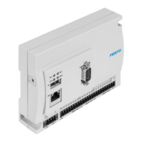
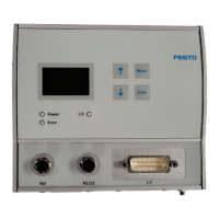
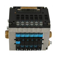
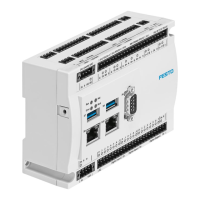
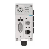
Festo Controller CECC
73
Feature CECC
Digital outputs
– Number 8
– Switching logic Positive logic (PNP)
– Contact Transistor
– Output voltage 24 V DC
– Output current 500 mA
– Electrical isolation Yes, via optocoupler
– Switching frequency Max. 1 kHz
– Short circuit proof Yes
– Status display LED
IO-Link (CECC-LK and CECC-S)
– Protocol Device V 1.0, master V 1.1
– Connection technology Cage Clamp connector
– Master: 5-pin
– Device: 3-pin
– Communication mode Can be configured via software
– Master, 5-pin: SIO, COM1, COM2, COM3
– Device, 3-pin: COM1, COM2, COM3
– Permissible length of IO-
Link cables
20 m
– Port type Device: A
Master: B
– Number of ports Device: 1
Master: 4 (CECC-LK)/1 (CECC-S)
– Master, output current 3.5 A/port
– Communication C/Q LED green
C/Q LED red
– Ready status display L+ LED green on
L+ LED green off
– Process data width OUT Master parameterisable 2 - 32 bytes
– Process data width IN Master parameterisable 2 - 32 bytes
– Memory Master 2 kBytes per port
– Minimum cycle time Device: 3.2 ms
Master: 5 ms
– Device ID 0x550000, 0x550001, 0x550002, 0x550003, 0x550004
Fieldbus interface
– Type CAN bus
– Connection technology Plug, Sub-D, 9-pin
– Transmission rate 10, 20, 50, 100, 125, 250, 500, 800, 1000 kbps
Can be set via software
– Electrical isolation Yes
USB interface USB 1.1
 Loading...
