3 Mounting and pneumatic installation
Festo – P.BE-CPX-CMAX-SYS-EN – en 2017-09b – English 21
3.3 Mounting of the drive and displacement encoder
Note
In order to avoid damage due to uncushioned movement into the end positions:
Use appropriate shock absorbers.
Determine software end positions.
To avoid damage to the displacement encoder when the displacement encoder is short
er than the stroke of the drive:
Limit the movement range by means of additional end stops.
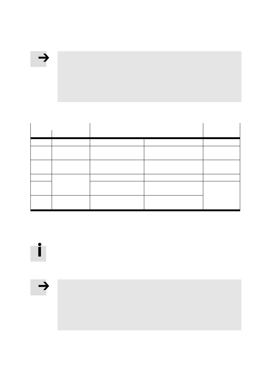
The following drives are approved starting with firmware V 2.2 for operation with the CMAX axis con
troller (at the time of printing):
Drive Displacement encoder Sensor inter
face
Type Design
DDLI Linear drive Integrated Digital (absolute) –
1)
DDPC Standard
cylinder
Integrated Incremental CASM-S-D3-R7
DGCI Linear actuator Permanently attached
at the factory
Digital (absolute) –
1)
DNCI Standard
cylinder
Integrated Incremental CASM-S-D3-R7
DNC
2)
External,
MLO-POT-LWG..
Potentiometer (absolute) CASM-S-D2-R3
DSMI Semi-rotary
drive
Integrated Potentiometer (absolute)
1) Not required
2) The slow speed variant S10, low friction variant S11, temperature resistant variant S6 are not permitted (only on request). Use
only DNC variants with permissible max. piston speed Vmax > 1 m/s.
Tab. 3.1 Permissible drives
Additional drives are in development.
Current information è www.festo.com/catalogue.
3.3.1 General requirements of the mechanical system
Note
Machine parts that tend to oscillate and mechanical play, e.g. between the cylinder
piston rod and the load to be moved, result in poor movement behaviour. Oscillations
and mechanical play confront the controller with “constantly changing loads”.
Fasten the axis to appropriate machine parts that are as rigid as possible.
Connect the drive, guide, displacement encoder and load as free of play as possible
and align them flush with each other.
 Loading...