4 Electrical installation
42 Festo – P.BE-CPX-CMAX-SYS-EN – en 2017-09b – English
4.3.1 Proportional directional control valve VPWP
The VPWP has an incoming (In) and outgoing (Out) axis connection (è Tab. 4.2).
DO connection; digital output for brake/clamping unit
The digital output (DO) at pin 2 permits connection of a valve for a brake or clamping unit. Control is
accomplished through the I/O data of the CMAX (è Communication profile description, P.BE-CPX-
CMAX-CONTROL-...).
Note
For the CMAX to have the correct control function, the clamping unit or brake must al
ways be switched with the following logic (è Fig. 4.2):
– Pin 2: 0 V = clamping unit/brake closed
– Pin 2: 24 V DC = clamping unit/brake open
Connection DO; load voltage output
The load supply voltage provided at pin 4 can also be used for switching a valve, for example when the
load voltage supply + 24 V DC (U
VAL
) fails (è Section 4.4.2).
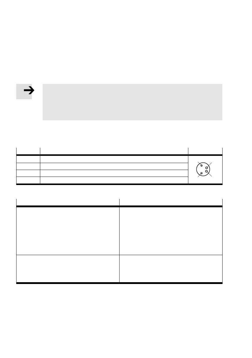
Pin Allocation DO
1 n.c. (not assigned)
4
2
3
1
2 Digital output (brake/clamping unit)
3 0 V
4 + 24 V DC voltage output (load voltage)
Tab. 4.4 Pin allocation of connection DO of the VPWP, M8 4-pin, socket
Technical data Value
Digital output (pin 2)
– Activation
– Supply
– Max. current
– Fuse protection
– Design
– Galvanic isolation
Via I/O data
From 24 V DC (U
VAL)
500 mA
Protected against short circuits
1)
Positive logic (PNP)
No
Voltage output (load voltage, pin 4)
– Supply
– Max. current
– Fuse protection
From 24 V DC (U
VAL)
500 mA
Protected against short circuits
1)
1) Temperature switch-off: Maximum short-circuit current (short term) is defined only by the cable and connection resistance.
Tab. 4.5 Technical data of connection DO