3 Mounting and pneumatic installation
30 Festo – P.BE-CPX-CMAX-SYS-EN – en 2017-09b – English
3.4.2 Mounting the VPWP proportional directional control valve
Attach the VPWP as close to the drive as possible according to one of the following alternatives.
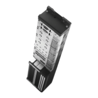
VPWP-4/-6/-8
a) Mounting on an even surface with two M3 screws and
one retaining washer each
The tightening torque is 1.5 N ±10 %.
Fig. 3.4
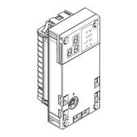
b) Mounting on the side with 4 M4 screws
The tightening torque is 3 Nm ±10 %.
Fig. 3.5
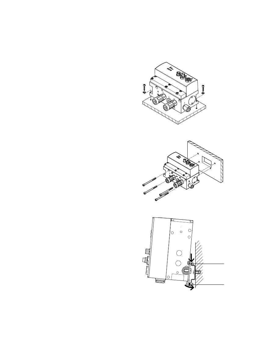
c) Mounting to an H-rail (DIN mounting rail size TH35)
Depending on the size of the VPWP, the following attach
ment is required (è www.festo.com/catalogue):
– VPWP-4/-6: CPASC1-BG-NRH
– VPWP-8: CPV10/14-VI-BG-NRH-35
1. Ensure that the mounting surface can carry the weight
of the VPWP.
2. Mount H-rail. Be sure to leave sufficient space for con
necting the supply cables and tubes.
1
2
Fig. 3.6
3. Screw mounting clips to the VPWP with the accompanying screws – tightening torque 1.5 Nm. Make
sure that the fixing bolts ( 1 ) of the clips grip into the groove of the VPWP.
4. Hang the VPWP on the H-rail. Secure against tipping or slipping by using the H-rail clamping ( 2 ).