4 Electrical installation
Festo – P.BE-CPX-CMAX-SYS-EN – en 2017-09b – English 41
4.3 Axis connection
The peripherals of the positioning system are connected at the axis connection X of the CMAX. The
VPWP proportional directional control valve is connected as the first component. The displacement
encoder or a sensor interface (depending on the cylinder type or displacement encoder) is connected to
the proportional directional control valve. These components together form the axis string. The follow
ing table shows the pin assignments of the axis connections of CMAX, VPWP and sensor interface
CASM.
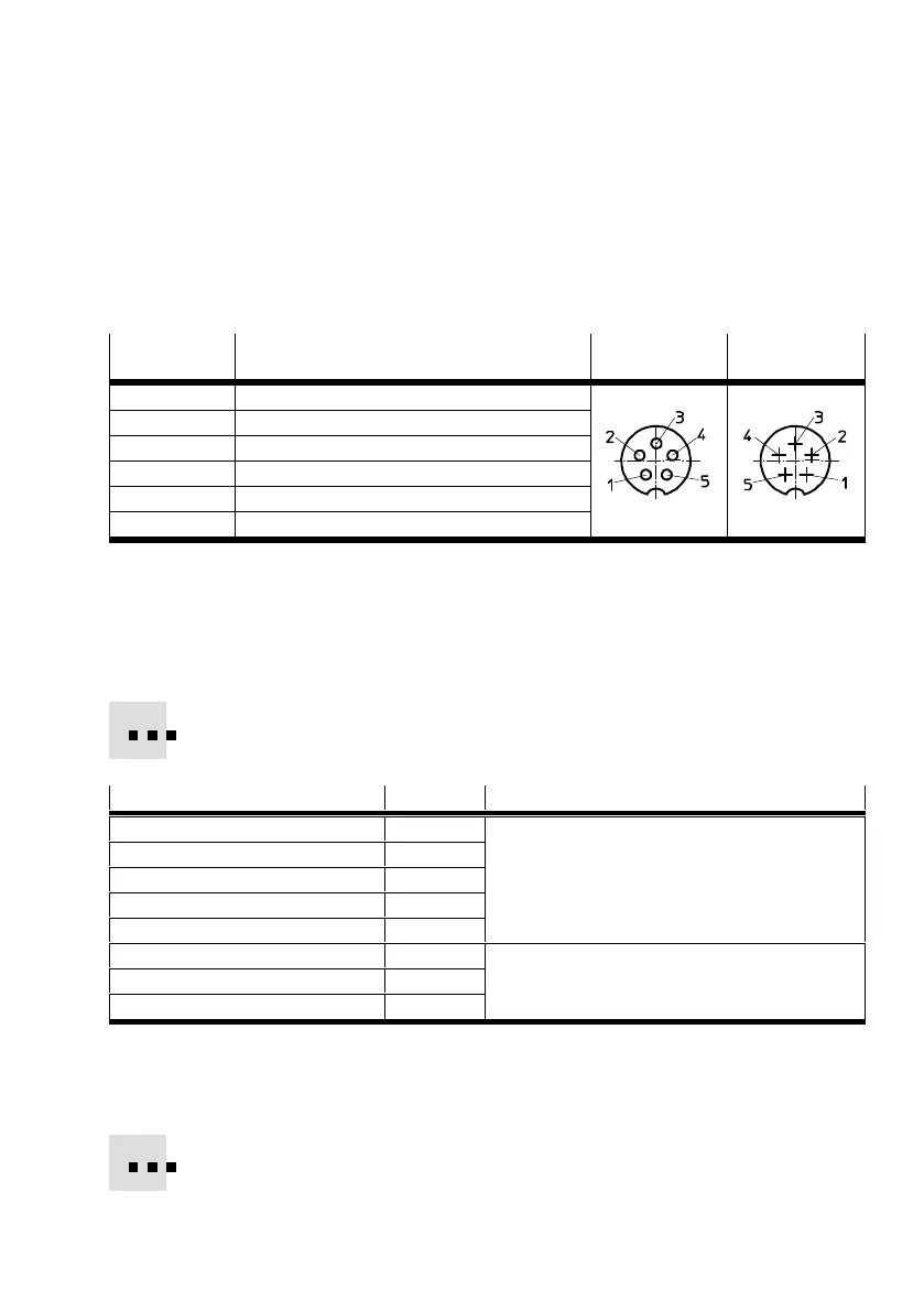
Pin Assignment CMAX: X
VPWP: Out
VPWP: In
CASM: S1
1 + 24 V DC operating voltage
2 + 24 V DC load voltage
3 0 V
4 CAN_H
5 CAN_L
Housing Cable screening
1)
1) Cable screening connected to the earth terminal at the VPWP
Tab. 4.2 Pin allocation of the axis connections
Axis string
The maximum permitted length (total) of the used connecting cables KVI-CP-3-... of the axis string is
30 m (total length CMAX – VPWP – sensor interface or displacement encoder).
Tab. 4.3 shows the recommended connecting cables.
Connecting cables
1)
Length Brief description
KVI-CP-3-WS-WD-0,25 0.25 m Angled plug connector and angled socket
KVI-CP-3-WS-WD-0,5 0.5 m
KVI-CP-3-WS-WD-2 2 m
KVI-CP-3-WS-WD-5 5 m
KVI-CP-3-WS-WD-8 8 m
KVI-CP-3-GS-GD-2 2 m Straight plug and straight socket
KVI-CP-3-GS-GD-5 5 m
KVI-CP-3-GS-GD-8 8 m
1) Cable between CMAX, VPWP, sensor interface, displacement encoder
Tab. 4.3 Connecting cables for the axis string
Cabinet through-hole
For the cabinet through-feed, we recommend the connecting component KVI-CP-3-SSD.